Configuration Mode (ConF)
Code Nam e / De s cription Adjustment range Factory setting
bSP
bSd
bLS
bnS
bnS0
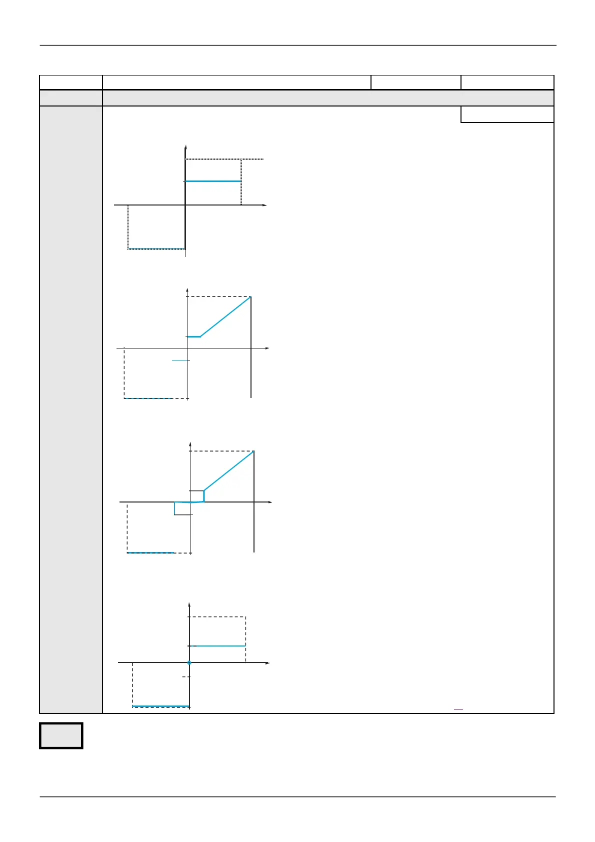
[Reference template]
[Standard]
(bSd)
[Standard]
(bSd)
Frequency
Reference
At zero reference the frequency = LSP
[Pe de s tal]
(bLS)
Frequency
HSP
-100%
LSP
Reference
LSP
+100%
At reference = 0 to LSP the frequency = LSP
HSP
[Deadband]
(bnS)
Frequency
HSP
-100%
LSP
Reference
0
LSP
+100%
At reference = 0 to LSP the frequency = 0
HSP
[Deadband 0]
(bnS0)
Frequency
This operation is the same as
[Standard]
(bSd), except that in
the follow ing cases at zero reference, the frequency = 0:
HSP
The signal is less than
[M in value]
, which is greater than 0
(example 1 V on a 2 - 10 V input)
The signal is greater than
[M in value]
, which is greater than
[M ax value]
(example: 11 V on a 10 - 0 V input).
If the input range is configured as "bidirectional", operation
-100%
0%
Reference
identical to
[Standard]
(bSd).
This parameter defines how the speed reference is taken into
account, for analog inputs and Pulse input only. In the case of the
PID regulator, this is the PID output reference.
The limits are set by the
[Low spe e d]
(LSP) and
[High s pe e d]
(HSP) parameters, page 87.
Parameter that can be modified during operation or w hen stopped.
Delinearization: For analog inputs only:
The input can be delinearized by configuring an interm ediate point on the input/output curve of this input:
HSP
LSP
-100%
LSP


 To Next Page