Configuration Mode (ConF)
Switching command
Depending on the num ber of m otors or s elected configurations (2 or 3), the switching com mand is s ent us ing
one or two logic inputs. The table below lis ts the pos sible combinations.
LI
2 m otors or configurations
LI
3 m otors or configurations
Num ber of configurations
or active m otors
0
0
0
1
0
1
0
1
2
1
1
2
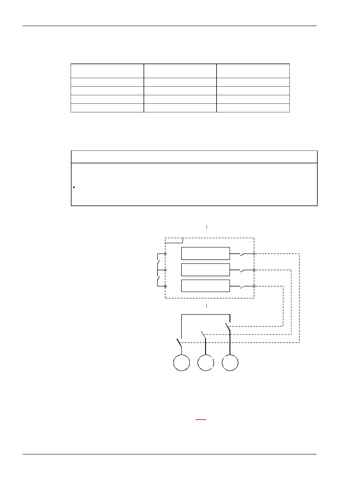
Schematic diagram for multimotor mode
Configuration 0
if the 2 contacts
are open
Configuration 1
Configuration 2
Auto-tuning in multimotor mode
This auto-tuning can be perform ed:
•
Manually us ing a logic input when the m otor changes.
•
Autom atically each tim e the m otor is activated for the 1
st
tim e after s witching on the drive, if the
[Automatic autotune]
(AUt) param eter on page 109 is s et to
[Yes]
(YES).
Motor thermal states in multimotor mode:
The drive helps to protect the three m otors individually. Each therm al s tate takes into account all stop tim es,
if the drive power is not switched off.
NOTICE
MOTOR OVERHEATING
The motor thermal state of each motor is not saved when drive is switched off.
When the drive is switched on, it is not aware of the thermal state of the connected motor or motors.
To enable correct temperature monitoring of the motors, install an external temperature sensor for each
motor.
Failure to follow these instructions can result in equipment damage.
Configuration 0
Configuration 1
Configuration 2


 To Next Page