Definition:
Input buffer RAM = input buffer EEPROM +17
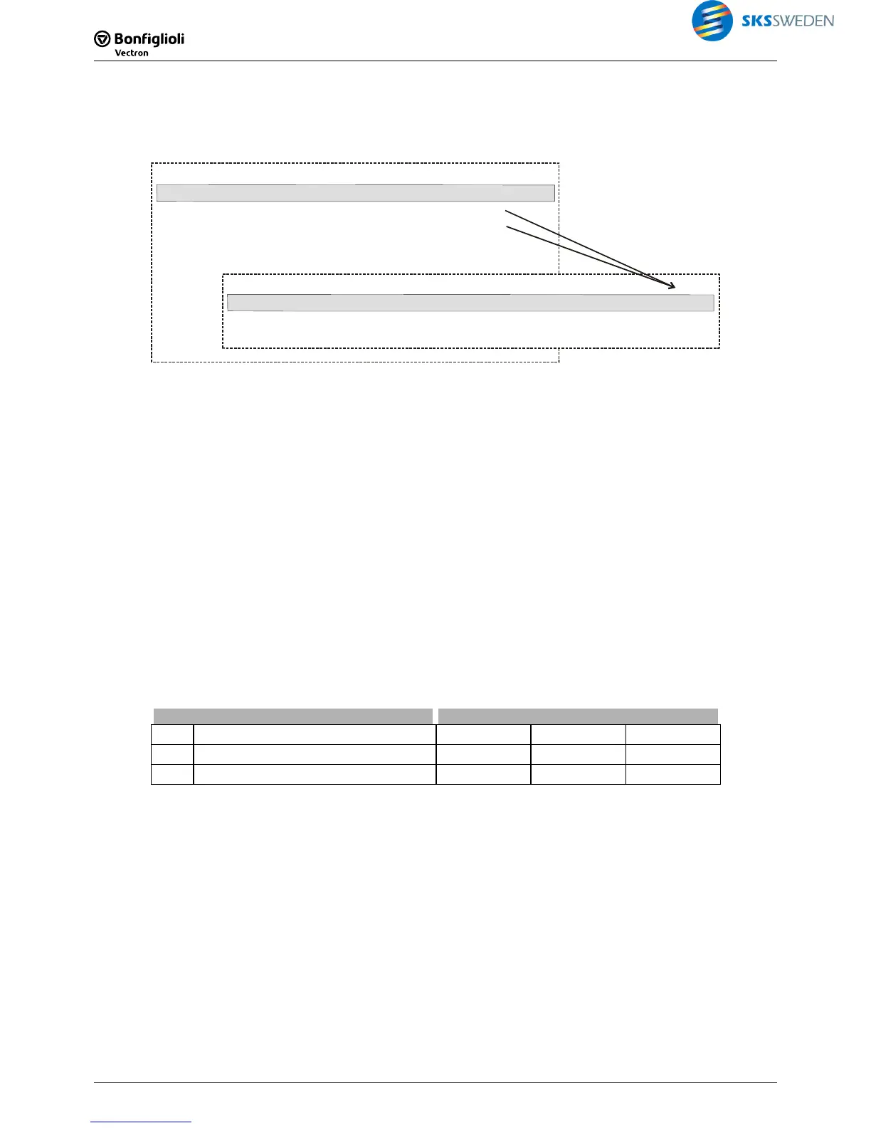
Write index and read index for the digital input buffer, example
FT-input buffer
1362
Parameter
Data set 0
3
FT-write index (FT-input buffer)
1360
3
FT-read index (FT-input buffer)
1361
VPlus
75 - S6IND
...
...
...
Function Table: input buffer
Index 3
VTable
75 - S6IND
Index 1
70 - Inverter Release
Index 2
71 - S2IND
FT-input buffer
1362
6.1.3 Write index and read index for the analog input buffer and FT
fixed values
Via the write and read indices, the index of the "Input buffer analog" table the parameters of
which are to be read or written is specified. VTable uses the parameters automatically for writ-
ing and reading. The write and read parameters are required for parameterization via the key-
pad of a control unit or via a bus system (e.g. PROFIBUS).
Write index and read index for parameterization and reading of "Input buffer ana-
log" table via software VPlus
The "Input buffer analog" table can be parameterized in the user interface VPlus or in the func-
tion table VTable. In the user interface VPlus, an index of the "Input buffer analog" table can be
created via parameter
FT-Write Index (FT Input analog) 1377. The chosen index corresponds
to a column in the "Input buffer analog" table. The settings of parameters
1379 to 1397 are
applied to the selected index of the "Input buffer analog" table. Via parameter
FT-Read Index
(FT-Input analog)
1378, the values of a selected index can be read from the "Input buffer
analog" table.
Parameters Setting
No. Description Min. Max. Fact. sett.
1377 FT-Write Index (FT-input analog) 0 9 1
1378 FT-Read Index (FT-input analog) 0 9 1
Settings for fixed parameterization
(non-volatile):
Settings for non-fixed parameterization
(volatile):
0: all input buffers in EEPROM 5: all input buffers in RAM
1 … 4: individual input buffer in EEPROM 6 … 9: individual input buffer in RAM
Note:
The settings "0" or "5" for FT Write Index (FT input analog) 1377 change all values of an in-
put buffer in the EEPROM or RAM.
In the case of non-volatile storage (0..4), the changed values are still available when power
supply is switched on again.
In the case of volatile storage (5…9), the data is only stored in RAM. If the unit is switched off,
this data is lost and the data required are loaded from EEPROM.

 Loading...


