dt
I2I1d
P2P1dtI2I1
P1
P1
I2I1P1O2O1
1-n1-n
n
1-n1 - n1 - n
n
1-n
1-n1-n1-n
−
× ×+
∫
−+−×=−=
•
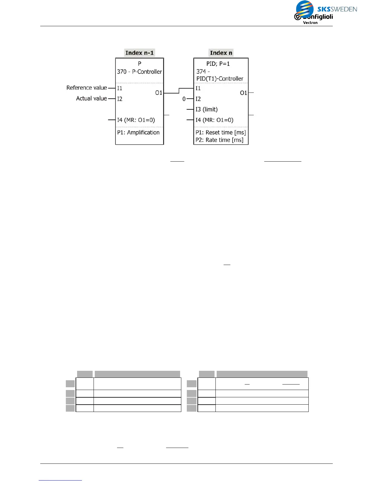
Set amplification in P controller.
• Set integral time and derivative action time in PID controller.
Note:
If the amplification of the PID controller is to be 1 , no P controller must be connected in series.
If a value of 100.00% is applied to the input in the form of a jump, the output value is the total
of the three components:
− P component: 100.00% constant
− I component: Ramp reaching the value of 100.00% after integral time P1.
− D component: Pulse of length of a sampling step and level
Abtastzeit1T%;100
1T
2P
=×
If the pulse level exceeds the limitation of the output value, the pulse will be output longer.
The output value is limited to the value at input I3.
Input I3 can be combined with a fixed value, for example.
As long as status TRUE is present at I4 (Master Reset), the output value O1 and the I compo-
nent are 0.
Note:
Percentages [%] have two decimals.
For example: Value 12345
IN
= 123.45% = 1.2345
5.4.6 [375] PID(T1) controller (Tn in seconds)
Type Function
Type Function
I1 % Input (reference value) O1 %
()()
()
dt
I2I1d
P2dtI2I1
P1
1
I2I1O1
−
×+
∫
−+ − =
I2 % Input (actual value) O2 % inverted output = -1
I3 % Limitation of output values P1 i Integral time in s
I4 b Master Reset P2 i Derivative action time in ms
Description:
The control deviation (I1 – I2) is multiplied by the amplification (=1). The I component and the
D component are added.
()
()

 Loading...


