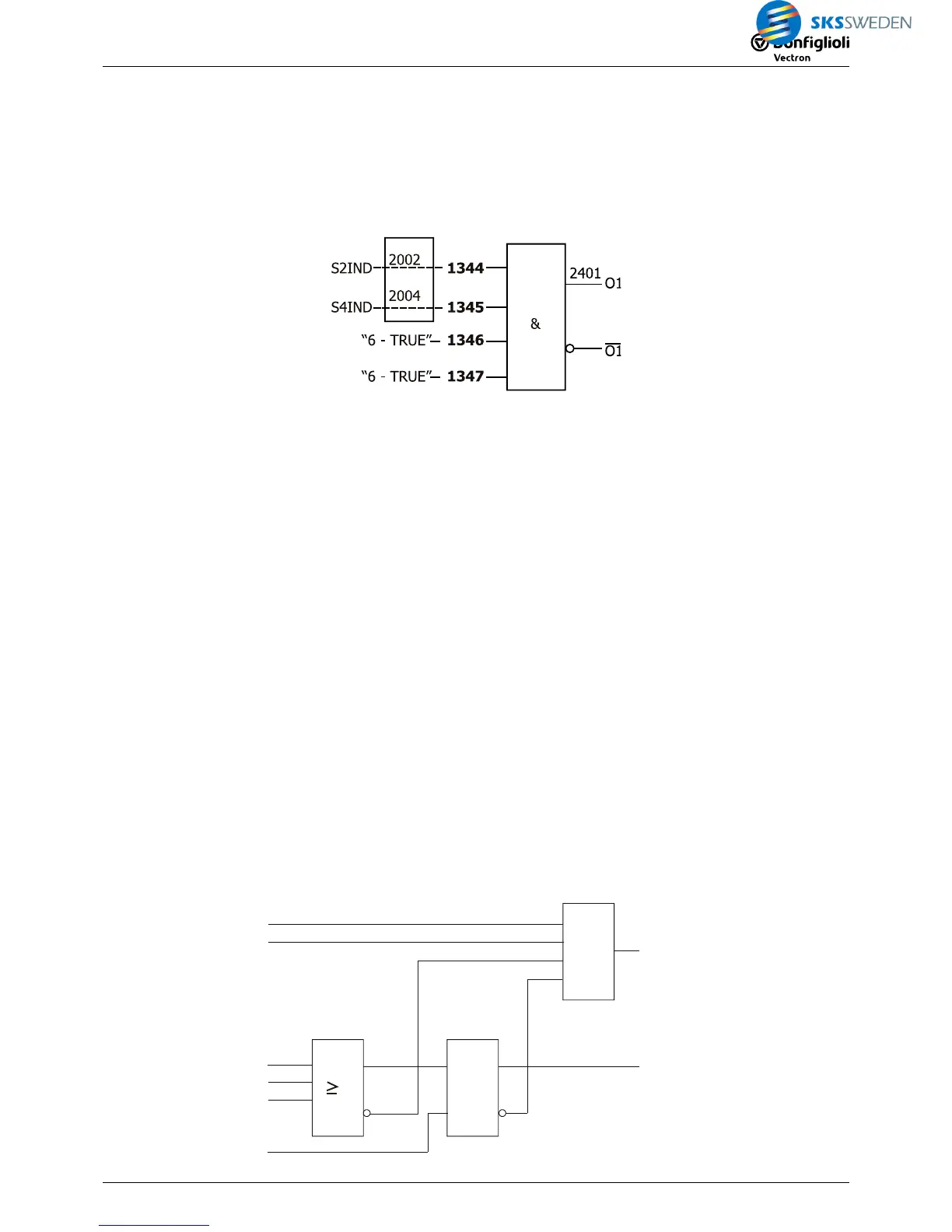
Settings in index 1 of function table:
FT Instruction 1343 = "1 - AND",
FT input 1 1344 = "2002 - FT input buffer 2",
FT input 2 1345 = "2004 - FT input buffer 4",
FT input 3 1346 = "6 - TRUE",
FT input 4 1347 = "6 - TRUE",
FT target output 1 1350 = "2401 - FT output buffer 1".
Settings in parameter group digital outputs:
Op. Mode Digital Output 1 530 = "80 - FT-Output Buffer 1".
6.4 Example 2: Combining several FT-instructions
Note:
The FT-instructions will be processed column by column according to the index in the table.
When designing application-specific logic links, in particular in the case of time-critical applica-
tions:
−
Make sure to follow the correct order of the FT-instructions.
− Note the processing time (1 ms per FT-instruction).
Example of parameterization of instructions in a function table:
Step 1: Task
The drive may only start if both start signals (Start 1 and Start 2) are present and no error is
present.
As soon as one of the two start signals (either Start 1 or Start 2) is no longer set, the drive is to
be stopped.
If one of three error messages (error 1, error 2 or error 3) is present, the drive is to be
stopped.
The acknow. input (Ack) is used for acknowledging the error messages.
Any error condition that may be present is to be signaled on digital output 1.
Step 2: Logic plan
start 1
start 2
Fault 1
Fault 2
Fault 3
A

 Loading...


