4.6.6 [180,181,182] Clock generator, Master
Type Function
Type Function
I1
b S clock generator 1
O1
b output O1
I2
b S¯ Clock generator 2
O2
b
negated output O2 =
1O
I3
b Master Set input
P1
t On-time (High)
I4
b Master Reset input
P2
t
Off time (Low)
180 [ms], 181 [s] or 182 [min]
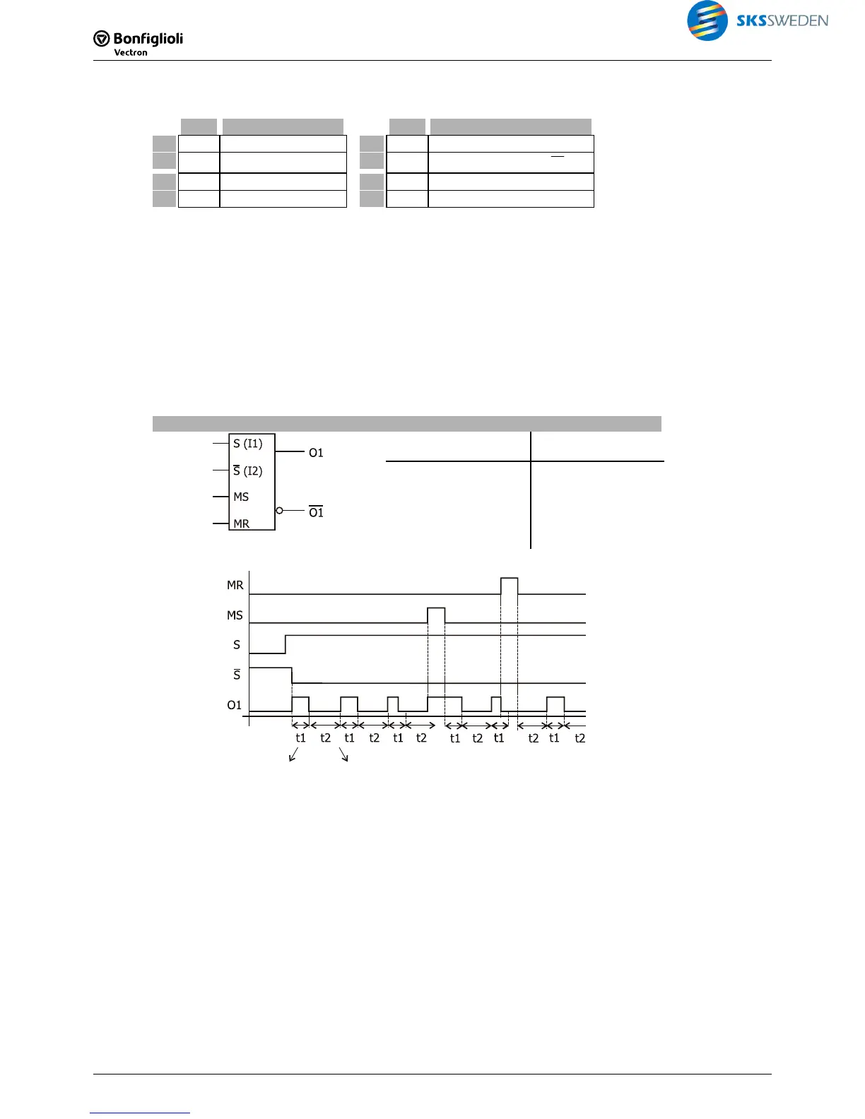
Description:
As long as input 1 is TRUE and input 2 is FALSE, the set pulse pattern is output. The pulse pat-
tern at the output always starts with TRUE. The clock pattern is defined by the on-time and the
off-time. The time set in P1 is the on-time (High) and the time set in P2 is the off-time (Low).
Via the output buffer, the output signal is globally available.
Master Set and Master Reset are connected parallel with the function and change the state of
the function as soon as the signal is present.
Clock generator, Master
S
S¯
MS
MR
O1
Q
State
x x x 1 0 Off (Master)
x X 1 0 1 On (Master)
x 1 0 0 0 Off
0 x 0 0 0 Off
1 0 0 0 t1 1 Clock On
1 0 0 0 t2 0 Clock Off
P1
(on-time)
P2
(off-time)

 Loading...


