4 Description of digital functions
In the following, you will find explanations and examples of the individual digital functions. The
term "digital function" is defined as follows:
A digital function has at least one digital input value but not analog input value. The output
value is always digital.
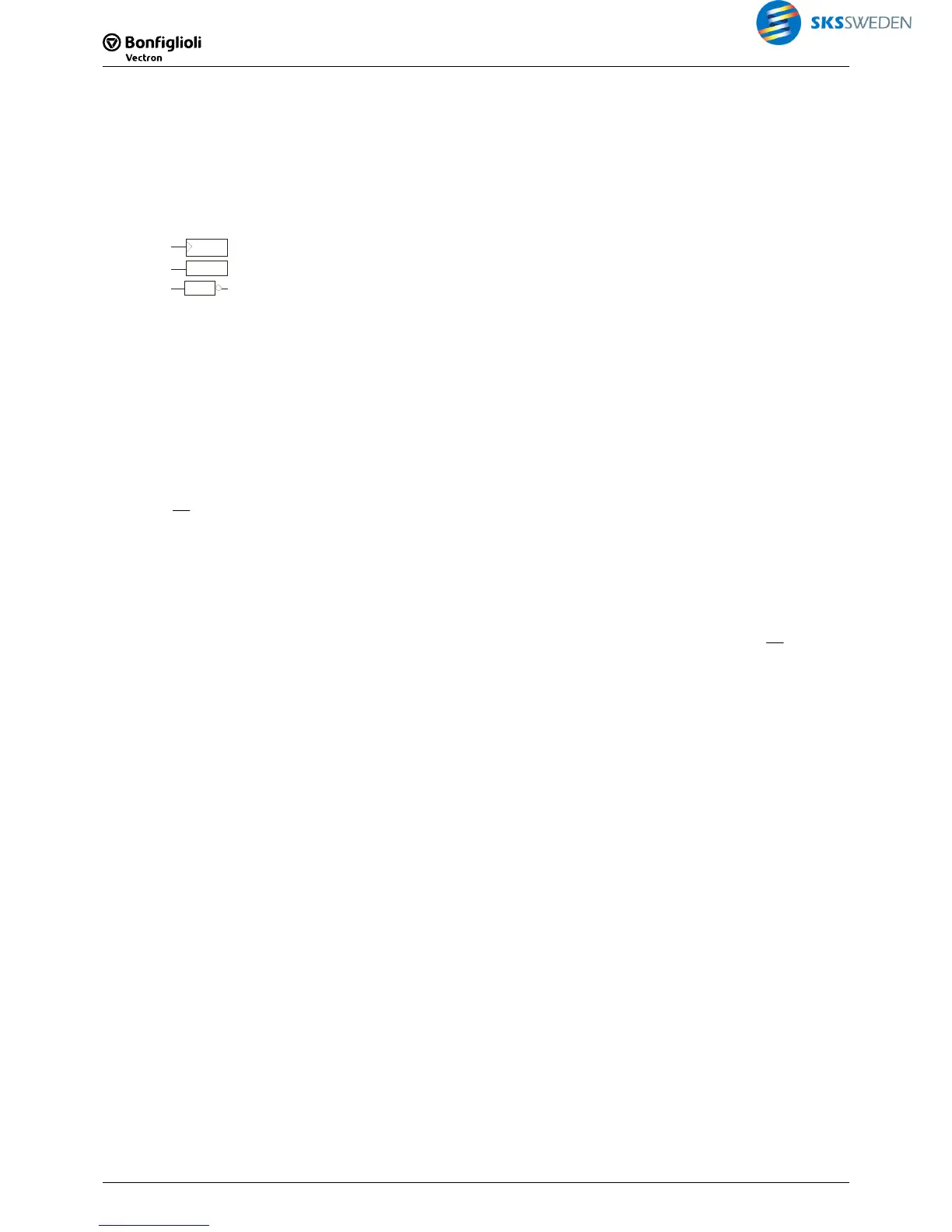
The following symbols are used in the diagrams:
C
edge evaluation
D
level evaluation
TT2
negated output
0 "Low" state. Representation of signal statuses in logic tables.
1 "High" state. Representation of signal statuses in logic tables.
FALSE "Low" state. Representation of signal statuses in function descriptions.
TRUE "High" state. Representation of signal statuses in function descriptions.
x any state ("Don’t care" – 0 or 1).
0 Æ 1
positive edge.
1 Æ 0
negative edge.
Q
n-1
last state is maintained.
Q
n-1
¯¯¯
last state is negated ("toggle").
O
n
non-negated output
n
O
negated output
P1
VPLC: Input field in function block setup,
Function table: Parameter
FT Parameter 1 1348
P2
VPLC: Input field in function block setup,
Function table: Parameter
FT Parameter 2 1349
Note:
For better clarity, output O
n
(non-negated) is used in the descriptions. The negated output
n
O
is available in each function and can be used.
For digital functions, note:
− Unused inputs must be set to "7 - Off".
Exception: Unused inputs of the instruction "AND" must be set to "6 - On".
− In all functions, output 2 has the inverted logic state of input 1.
− Clock inputs (T, C) evaluate signal edges.
− Set/Superior-Set/Master-Set inputs and Reset/Superior-Reset/Master-Reset inputs evaluate
logic states.
− Reset has priority over Set.
− Times set for P1 and P2, are limited internally to a max. value of 24 days.
Via the library, the logic function can be selected.
 Loading...


