2.2.5 Digital input block
Combining a digital function block input with a digital input (terminal) or a frequency inverter
control signal:
− Drag a block DigIn from the library to the function block input.
− Double-click the block DigIn.
− Select an input buffer for the PLC signal.
− As the global source, select the digital input or control signal to be applied to the functional
module input.
2.2.6 Analog input block
Combining an analog function block input to a analog input (terminal) or a frequency inverter
signal:
− Drag a block "Analog In" from the library to the function block input.
− Double-click the block "Analog In".
− Select a physical quantity or percent for the PLC signal.
− Select percent if a signal at the analog input (terminal) of the frequency inverter is to be
applied to the function block input.
− As the global source, select the signal to be applied to the functional module input.
2.2.7 Digital output block
Combining a digital function block output with a device function or a digital output (terminal):
− Drag a block DigOut from the library to the function block output.
− Double-click the block DigOut. Select an output buffer.
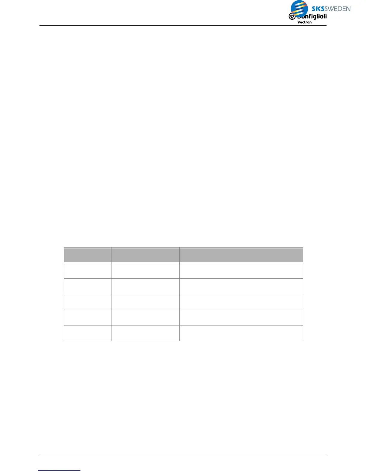
Example:
Selected output
buffer
Signal source for de-
vice function
Example of device function
1 2401
Start Anticlockwise 69
= 2401 – PLC-Output buffer 1
4 2404
Error acknowledgment 103
= 2404 – PLC-Output buffer 4
Signal source for digital
output (terminal)
Example of digital output (terminal)
1 80
AgilE:
Operation mode
OUT1D (X13.5) 531
= 80 – PLC-Output buffer 1
4 83
ACU:
Operation mode digital output 1 530
= 83 – PLC-Output buffer 4

 Loading...


