For control of a PLC it is sufficient to select a mode and set it accordingly. When the instruction
block was processed, the frequency inverter resets the operation mode to "0-Stop" automatical-
ly. The same mode can be selected again.
Note:
If a diagnosis via VPlus is to be performed, both modes are required. Execution of the instruc-
tion block must be started by the modes alternately, because VPlus only updates parameters
(on ACU) which have been changed.
Note:
If "Single Step", "Single Part" or "Single Cycle" are selected, the selected mode is maintained.
The status of the function table is shown exactly in
FT-Actual Values Function 1356 .
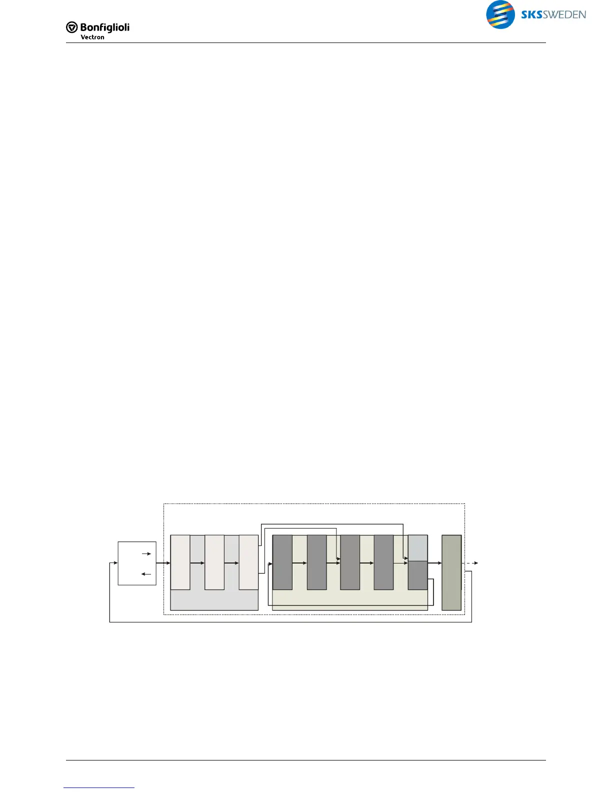
6.2.1 Example Run/Stop
The following diagram shows a function block circuit which includes two jump functions (J1 and
J2). Depending on the settings of parameter
FT-RunMode 1399 , the procedure is as follows:
FT-Runmode 1399 = "1 – Run"
The sequence is processed continuously. Jump functions are processed according to input sta-
tuses.
FT-Runmode 1399 = "11 – Single Step", "12 – Single Step"
The sequence is interrupted after each instruction. Each time, the sequence is stopped, FT-
RunMode
1399 must be restarted with "11 – Single Step" or "12 – Single Step". Jump functions
are processed according to input statuses. Thus, the sequence is "I=1, Stop"; "I=2, Stop";…
FT-Runmode 1399 = "21 – Single Part", "22 – Single Part"
The sequence is processed until a jump instruction is reached which writes the output buffer. In
this example, the buffer is written by both jump instructions. Thus, the sequence is "Block A,
Stop"; "Block B, Stop";…
FT-Runmode 1399 = "31 – Single Cycle", "32 – Single Cycle"
The sequence is processed until the end is reached and the return jump to the start is effected
(to block C). It may happen that Block B is processed repeatedly depending on the digital sig-
nals if the jump at J2 jumps to the beginning of Block B. A cycle may be, for example: "Block A,
Block B, Block B, Block B, Block C, return jump, stop".
I=1
I=2
I=3
...
...
...
20xx
24xx
I=4
...
I=5
...
I=6
...
JMP
J1
A
I=7
...
I=8
...
I=9
...
JMP
B
J2
C
6.3 Example 1: Combining two digital outputs
Digital signals S2IND and S4IND are to control digital output S1OUT. If both signals are
present, the output is TRUE. If not, the output is FALSE.

 Loading...


