Actual values of digital instructions
The actual values of an instruction are indicated by parameter
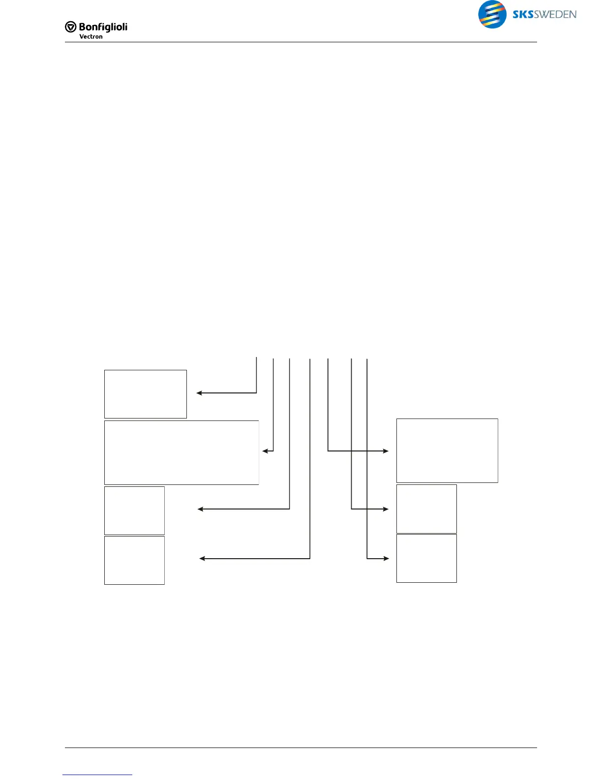
PLC Actual values function
1356. From left to right, the following is displayed:
−
state of PLC or function table (e.g. started, stopped)
− Index number of selected instruction vie
PLC read index (PLC input buffer) 1361
− Inputs of selected instruction
− Outputs of selected instruction
−
index number of last processed instruction
− Inputs of last processed instruction
− Outputs of last processed instruction
The states of the function table are:
R: Running – function table or PLC started
S: Stopped – function table or PLC stopped
U: Updating – input and output buffer are being updated
E: Empty – function table or PLC is empty
I: Initialization
Example
R01:.... !. 03:!..! .!”
R
St
f
ate of
unction table
01:
dex of instruction selected via
-read index (FT-input buffer)
1361
In
FT
.
1
F
. . .
2 3 4
T-inputs
!
FT
.
1 2
-outputs
03:
last processed
instruction
! . . !
1 2 3 4
FT-inputs
. !
1 2
FT-outputs
"." = FALSE
"!" = TRUE
Note:
For information on other actual values, refer to the operating instructions of the frequency in-
verter.

 Loading...


