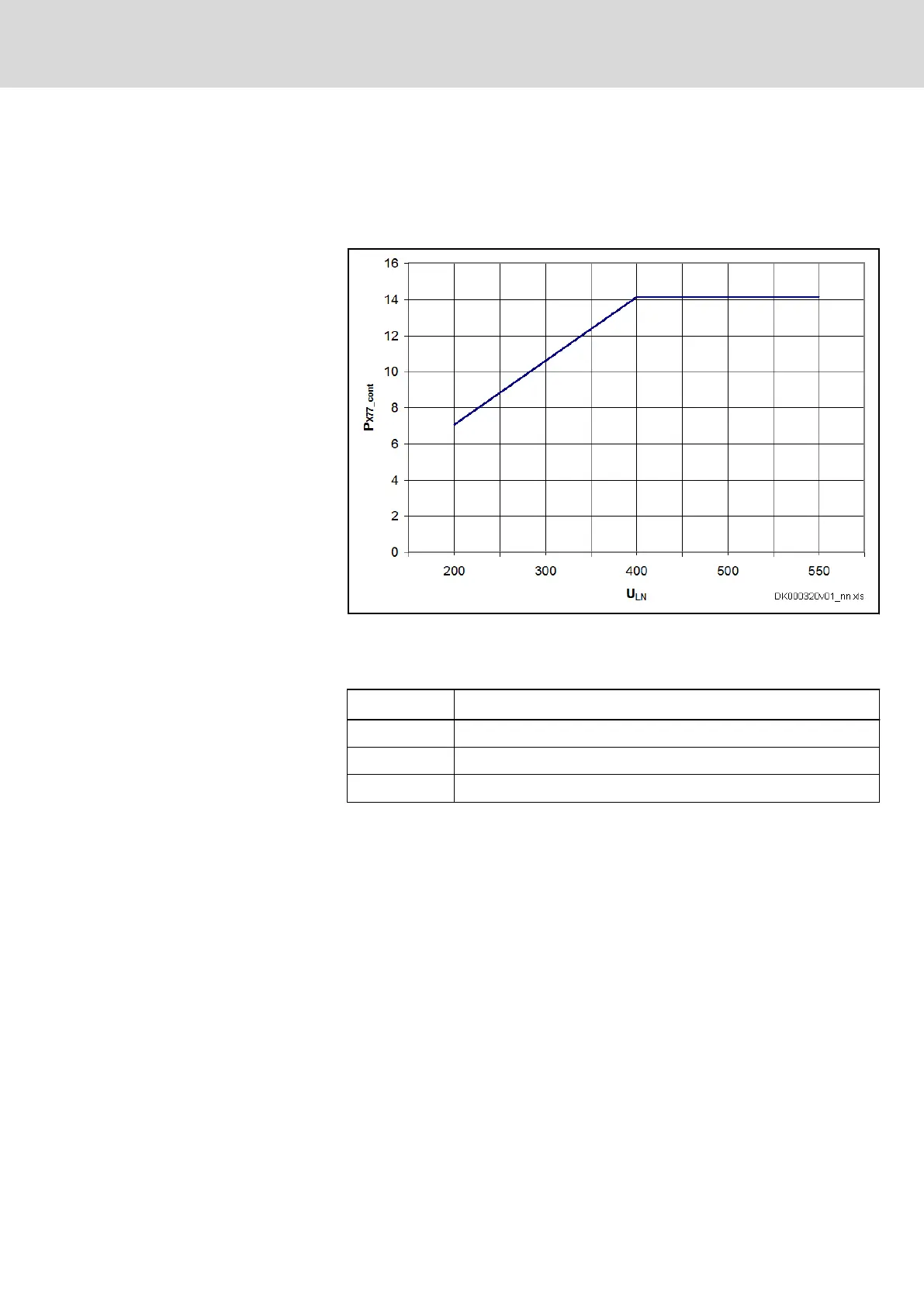
● the maximum continuous power which can be looped through via the
DC bus connector X77
(The continuous power results from the current carrying capacity of the
DC bus connector X77 and the mains voltage value.)
Load of DC Bus Connector at I = 25 A:
U
LN
Mains voltage
P
X77_cont
Continuous power at DC bus connector X77
Fig. 4-33: Load of DC Bus Connector
V
LN
P
X77_cont
200 V AC 7 kW
400 V AC 14 kW
500 V AC 14 kW
Tab. 4-42: Selected values of continuous power via DC bus connector X77
(P
X77_cont
) depending on mains voltage
Number of supplied devices:
If the sum of power reserves (P
reserve
) of the supplying devices is greater then
the continuous power of X77 (P
X77_cont
), the maximum number of supplied de‐
vices results from P
X77_cont
minus the respective DC bus continuous power of
the individual devices at average speed.
If the sum of power reserves (P
reserve
) of the supplying devices is smaller than
the continuous power of X77 (P
X77_cont
), the maximum number of supplied de‐
vices results from P
reserve
minus the respective DC bus continuous power of
the individual devices at average speed.
DOK-INDRV*-HCS01******-PR05-EN-P Bosch Rexroth AG 109/341
Rexroth IndraDrive CsDrive Systems with HCS01
Combining the individual components

 Loading...


