Data Symbol Unit min. typ. max.
Output current
I
Out
mA - - 20
Output frequency f MHz - - 1
Load capacitance between output
and 0 V
nF - - 10
Terminating resistor at load
R
Term
ohm 150-180
Overload protection - - Present
Short circuit protection - - Present
Tab. 7-13: Differential outputs
The differential output corresponds to the RS422 specifications.
On the control side, a line terminating resistor has to be available
for the SSI data signal. If this resistor is not available, connect an
external line terminating resistor (150-180 ohm).
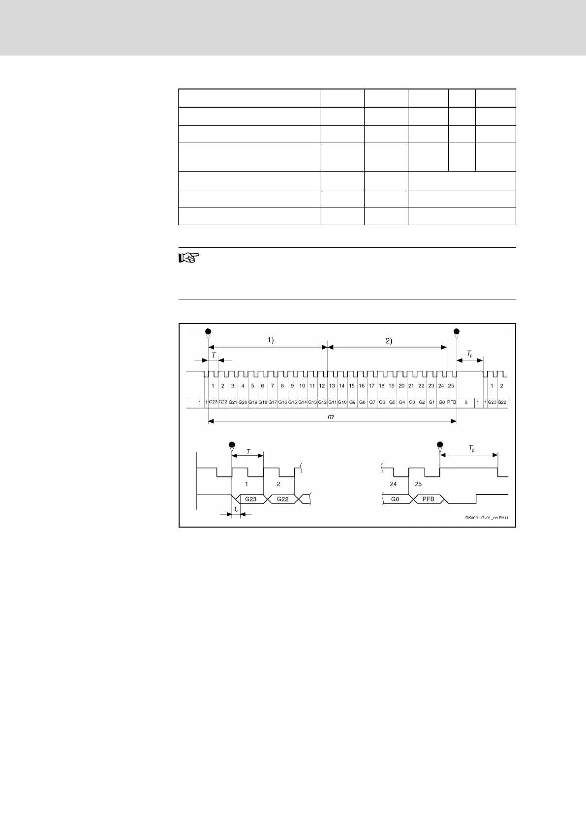
Pulse diagram
1) Resolution for 4096 revolutions
2) Resolution for 1 revolution
G0 Least significant bit in Gray code
G23 Most significant bit in Gray code
m Stored parallel information
T Clock time
T
p
Clock break ≥ 20 μs
t
v
Max. delay 200 ns
PFB Power failure bit (not used and always logically LOW)
Fig. 7-23: Pulse diagram with absolute actual position value output (SSI for‐
mat)
Bosch Rexroth AG DOK-INDRV*-HCS01******-PR05-EN-P206/341
Rexroth IndraDrive CsDrive Systems with HCS01
Technical data of the components

 Loading...


