X30, PROFIBUS PB
Description
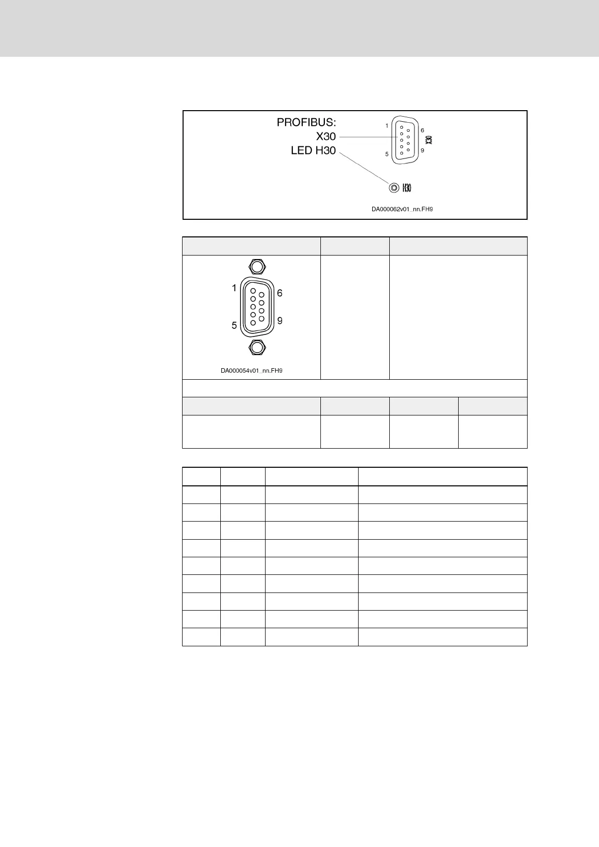
Fig. 6-16: PROFIBUS Interface
View Identification Function
X30 PROFIBUS PB
D-Sub, 9-pin, female Unit Min. Max.
Connection cable
Stranded wire
mm
2
0,08 0,5
Tab. 6-25: Function, Pin Assignment, Properties
Pin Assignment
Pin DIR Signal Function
1 - n. c.
2 - n. c.
3 I/O RS485+ Receive/transmit data-positive
4 O CNTR-P Repeater control signal
5 0 V 0 V
6 O +5 V Repeater supply
7 - n. c.
8 I/O RS485- Receive/transmit data-negative
9 0V 0 V
Tab. 6-26: Signal Assignment
Shield Connection
Via D-sub mounting screws and metallized connector housing.
Compatibility of the Interface
According to DIN EN 50 170
Recommended Cable Type
According to DIN EN 50 170 - 2, cable type A
Bus Connectors
The PROFIBUS connectors each have a connectable terminating resistor.
The terminating resistor must always be active at both the first and last bus
node. Carry out the connection as shown in the figures below.
Bosch Rexroth AG DOK-INDRV*-HCS01******-PR05-EN-P162/341
Rexroth IndraDrive CsDrive Systems with HCS01
Mounting and installation

 Loading...


