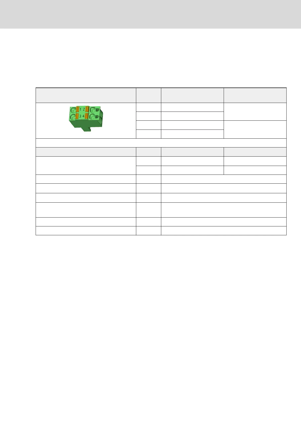
X13, 24V Supply (Control Voltage)
Function, Pin Assignment
The external 24V supply is applied via connection point X13 for
● the control section and power section of the drive controller
● brake control via X6
● the digital inputs and the digital output to X31 / X32
View Connec‐
tion
Signal name Function
1 0V Reference potential for pow‐
er supply
2 0V
3 +24V Power supply
4 +24V
Spring terminal (connector) Unit Min. Max.
Connection cable
Stranded wire
mm
2
1,0 2,5
AWG 16 12
Stripped length mm 10
Power consumption W P
N3
(see data for control voltage)
Voltage load capacity V U
N3
(see data for control voltage)
Current carrying capacity "looping through" from
0V to 0V, 24V to 24V
A 10
Polarity reversal protection Within the allowed voltage range by internal protective diode
Insulation monitoring Possible
Tab. 6-10: Function, Pin Assignment, Properties
Notes on Installation
Requirements on the connection to the 24V supply:
● Minimum cross section: 1 mm
2
● Maximum allowed inductance: 100 µH (2 twisted single strands, 75 m
long)
● Parallel line routing where possible
Depending on the power consumption of the devices and the current carrying
capacity of the connector X13, check via how many devices one line for 24V
supply can be looped through. You might possibly have to connect another
device directly to the 24V supply and then loop through the control voltage
from this device to other devices.
DOK-INDRV*-HCS01******-PR05-EN-P Bosch Rexroth AG 143/341
Rexroth IndraDrive CsDrive Systems with HCS01
Mounting and installation

 Loading...


