Absolute encoder emulation (SSI format)
Connection
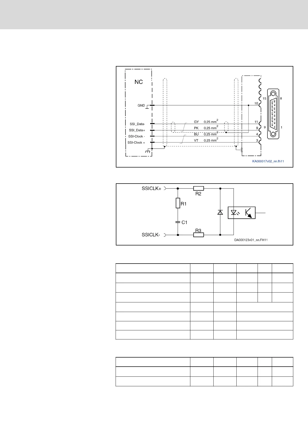
Fig. 7-21: Output of absolute actual position values according to SSI format
Fig. 7-22: Differential input circuit (block diagram)
Electrical data
Differential inputs, absolute encod‐
er emulation
Data Symbol Unit min. typ. max.
Input voltage "high"
U
In_High
V 2.5 - 5
Input voltage "low"
U
In_Low
V 0 - 0.5
Input resistance (difference)
R
In_D
ohm 110 - 130
Input resistance
R
In
kOhm 150
Clock frequency f kHz 100-1000
Overload protection - - Present
Short circuit protection - - Present
Tab. 7-12: Differential inputs
Differential outputs, absolute en‐
coder emulation
Data Symbol Unit min. typ. max.
Output voltage "high"
U
Out_High
V 2.5 - 5
Output voltage "low"
U
Out_Low
V 0 - 0.5
DOK-INDRV*-HCS01******-PR05-EN-P Bosch Rexroth AG 205/341
Rexroth IndraDrive CsDrive Systems with HCS01
Technical data of the components

 Loading...


