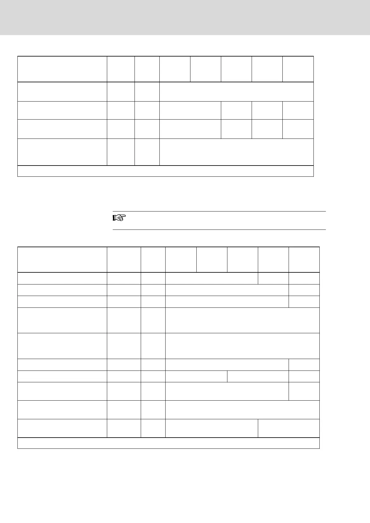
Description Symbol Unit
HCS01.1E
-W0005-
_-03
HCS01.1E
-W0008-
_-03
HCS01.1E
-W0018-
_-03
HCS01.1E
-W0028-
_-03
HCS01.1E
-W0054-
_-03
Monitoring value minimum DC bus
voltage, undervoltage threshold
U
DC_lim‐
it_min
V
0.75 x U
LN
or "P-0-0114, Undervoltage threshold", if
P-0-0114 > 0.75 x U
LN
Charging resistor continuous pow‐
er
P
DC_Start
kW 0.03 0.05 0.15 0.50
Allowed external DC bus capaci‐
tance (nom.) at U
LN_nenn
1)
C
DCext
mF - 3.00 4.00 13.00
Charging time at maximum al‐
lowed C
DCext
external DC bus ca‐
pacitance at U
LN_nenn
t
lade_DC_Ce
xt
s 2.50
Last modification: 2014-12-19
1) Use assigned mains choke
Tab. 7-45: HCS - Power section data - DC bus
7.3.4 Integrated braking resistor
Information on the external braking resistor: See chapter 8.3.4
"External braking resistors HLR" on page 301.
Integrated braking resistor data
Description Symbol Unit
HCS01.1E
-W0003-
_-02
HCS01.1E
-W0006-
_-02
HCS01.1E
-W0009-
_-02
HCS01.1E
-W0013-
_-02
HCS01.1E
-W0018-
_-02
Braking resistor continuous power
P
BD
kW 0.02 0.03 0.15
Braking resistor peak power
P
BS
kW 1.68 2.24
Nominal braking resistor
R
DC_Bleeder
ohm 100 68
Braking resistor switch-on thresh‐
old - independent of mains volt‐
age
1)
U
R_DC_On_f
V 390
Braking resistor switch-on thresh‐
old - depending on mains volt‐
age
2)
U
R_DC_On_v
-
Maximum allowed on-time duty
t
on_max
s 0.20 1.34
Minimum allowed cycle time
T
cycl
s 16.80 11.20 20.00
Regenerative power to be absor‐
bed
W
R_max
kWs 0.40 3.00
Balancing factor for P
BD
(for paral‐
lel operation at common DC bus)
f -
Cooling of integrated braking re‐
sistor
Natural convection Forced ventilation
Last modification: 2012-05-16
1) 2) Factory setting
Tab. 7-46: HCS - Integrated braking resistor data
Bosch Rexroth AG DOK-INDRV*-HCS01******-PR05-EN-P242/341
Rexroth IndraDrive CsDrive Systems with HCS01
Technical data of the components

 Loading...


