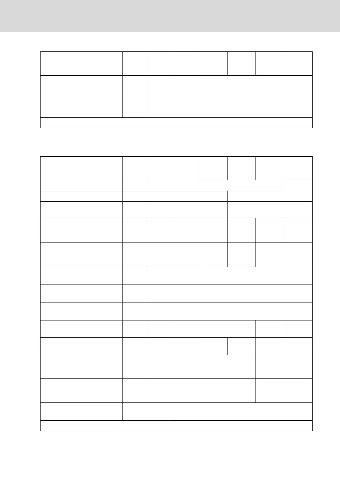
Description Symbol Unit
HCS01.1E
-W0003-
_-02
HCS01.1E
-W0006-
_-02
HCS01.1E
-W0009-
_-02
HCS01.1E
-W0013-
_-02
HCS01.1E
-W0018-
_-02
Allowed external DC bus capaci‐
tance (nom.) at U
LN_nenn
1)
C
DCext
mF -
Charging time at maximum al‐
lowed C
DCext
external DC bus ca‐
pacitance at U
LN_nenn
t
lade_DC_Ce
xt
s 2.50
Last modification: 2012-05-16
1) Use assigned mains choke
Tab. 7-44: HCS - Power section data - DC bus
Power section data - DC bus
Description Symbol Unit
HCS01.1E
-W0005-
_-03
HCS01.1E
-W0008-
_-03
HCS01.1E
-W0018-
_-03
HCS01.1E
-W0028-
_-03
HCS01.1E
-W0054-
_-03
DC bus voltage
U
DC
V ULN x 1.41
Capacitance in DC bus
C
DC
mF 0.11 0.39 0.78
DC resistance in DC bus (L+ to
L-)
R
DC
kOhm 320.00 230.00 136.00
Rated power (t > 10 min) at f
s
= 4
kHz; U
LN_nenn
; control factor a
0
>
0.8; with mains choke
P
DC_cont
kW - tbd 4.00 14.00
Rated power (t > 10 min) at
f
s
= 4 kHz; U
LN_nenn
; control factor
a
0
> 0.8; without mains choke
P
DC_cont
kW 0.46 0.86 1.70 2.60 9.00
Factor to reduce P
DC_cont
at single-
phase mains voltage
f
1_3ph
1-phase operation not allowed
P
DC_cont
and P
DC_max
vs. mains in‐
put voltage; U
LN
≤ U
LN_nenn
%/V
P
DC_cont (ULN)
= P
DC_cont
x [1 - (400 - U
LN
) x 0.0025]
P
DC_cont
and P
DC_max
vs. mains in‐
put voltage; U
LN
> U
LN_nenn
%/V No power increase
Maximum allowed DC bus power
at U
LN_nenn
; with mains choke
P
DC_max
kW - 9.70 19.00
Maximum allowed DC bus power
at U
LN_nenn
; without mains choke
P
DC_max
kW 1.38 2.58 5.10 6.20 14.00
Balancing factor for P
DC_cont
(for
parallel operation at common DC
bus) with mains choke
- 0.80
Balancing factor for P
DC_cont
(for
parallel operation at common DC
bus) without mains choke
- 0.50
Monitoring value maximum DC
bus voltage, switch-off threshold
U
DC_lim‐
it_max
V 900
Last modification: 2014-12-19
DOK-INDRV*-HCS01******-PR05-EN-P Bosch Rexroth AG 241/341
Rexroth IndraDrive CsDrive Systems with HCS01
Technical data of the components

 Loading...


