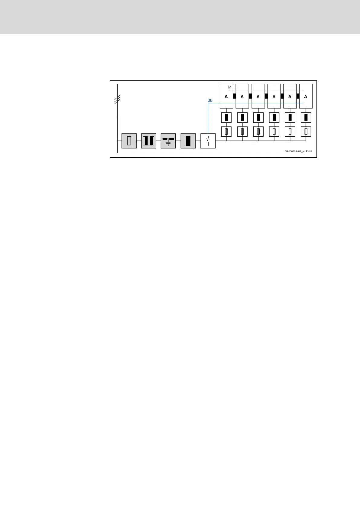
Supply via all devices
Use this type of DC bus coupling if you exclusively use one HCS01 device
type in your application.
Components marked with gray background color: Optional, de‐
pending on the application; the choke is used to reduce current
harmonics
A Component HCS01 (all components A identical); connected to
supply mains via balancing chokes; interconnected via DC bus
Bb Bb relay contact wiring
M Module bus (not obligatory)
Fig. 4-32: Group Supply; all HCS01 Components Connected to Supply Mains
Features
● All devices have to be of the same type
● DC bus continuous power of the supplying devices reduced by parallel
operation
● Energy compensation between the devices is possible (the DC bus ca‐
pacitors of the devices are connected in parallel)
● Balancing of the integrated braking resistors exists (equal load of all
braking resistors integrated in the devices)
● Balancing chokes or balancing resistors required in supply feeder
● It is possible to connect DC bus capacitor units
● Wiring effort for the mains connection of all devices relatively big
● DC bus short circuit functionality has to be realized externally, if required
Implementing the DC bus coupling
Maximum number of devices
A maximum of 8 devices can be coupled at a common DC bus.
The maximum number of devices which can be interconnected via DC bus
coupling depends on
● the power reserves of the supplying devices
(The power reserve (P
reserve
) results from the difference between the
possible DC bus continuous power of the device and the power con‐
sumed by the motor connected to the device.)
● the type of DC bus connection:
– Connection looped through via DC bus connector X77
– DC bus connecting bar with spur lines to the individual devices
● the sum of DC bus continuous powers of all supplied devices
● the mains voltage value
Bosch Rexroth AG DOK-INDRV*-HCS01******-PR05-EN-P108/341
Rexroth IndraDrive CsDrive Systems with HCS01
Combining the individual components

 Loading...


