HCS01.1E-xxxxx-x-03
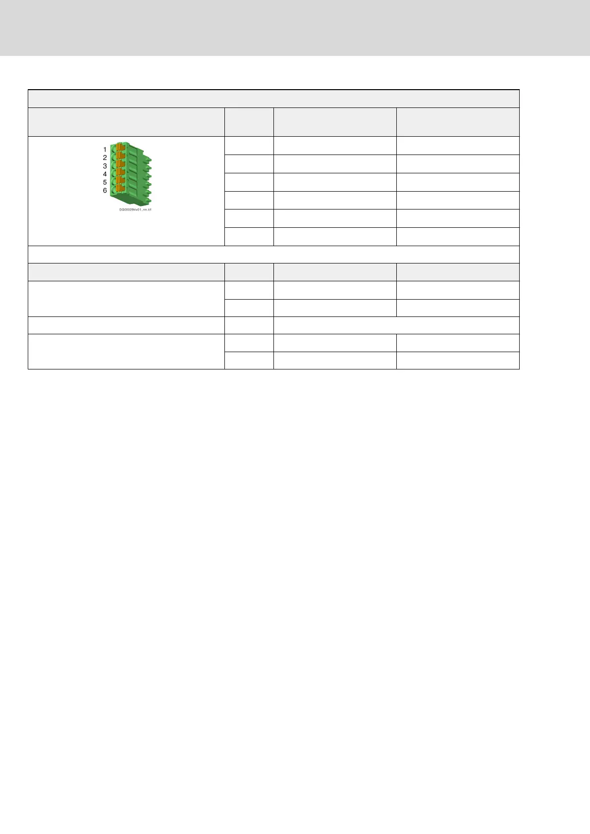
View Connec‐
tion
Signal name Function
1 Rel1
Bb relay contact
1)
2 Rel2
Bb relay contact
1)
3 Mod1
Module bus
2)
4 Mod2
Module bus
2)
5 0V_Mod
Module bus GND
2)
6 0V_Mod
Module bus GND
2)
Spring terminal (connector) Unit min. max.
Connection cable
Stranded wire
mm
2
0.2 1.5
AWG 24 16
Stripped length mm 10
Contact rating V 30
A 0.01 1
1) Wire the Bb relay contact in the control circuit for mains con‐
nection (see chapter "Control Circuit for the Mains Connection"
on page 104). When the contact opens, the mains contactor
must interrupt the power supply. If multiple devices supply the
DC bus (group supply), connect the Bb relay contacts (X47) of
all supplying devices in series.
2) The pins 3, 4 and 5, 6 are jumpered. This allows the module
bus to be looped through from one device to the next.
Tab. 6-18: Function, pin assignment, properties
Module bus connections
Maximum allowed length of an individual module bus connection: 10 m
In the following cases, use shielded cables for the module bus connection:
● The length of an individual module bus connection is > 0.5 m.
● The total length of all module bus connections of the drive system is
> 3 m.
Use shielded cables with a conductor gauge ≥ 2 × 0.5 mm
2
.
Accessory for shield connection: HAS09.1-001-NNN-NN (see chapter " Mod‐
ule bus cable shield connection" on page 256).
Technical data
chapter "Relay Contact Type 2" on page 229
Bosch Rexroth AG DOK-INDRV*-HCS01******-PR05-EN-P150/341
Rexroth IndraDrive CsDrive Systems with HCS01
Mounting and installation

 Loading...


