Technical data of EC encoder evaluation
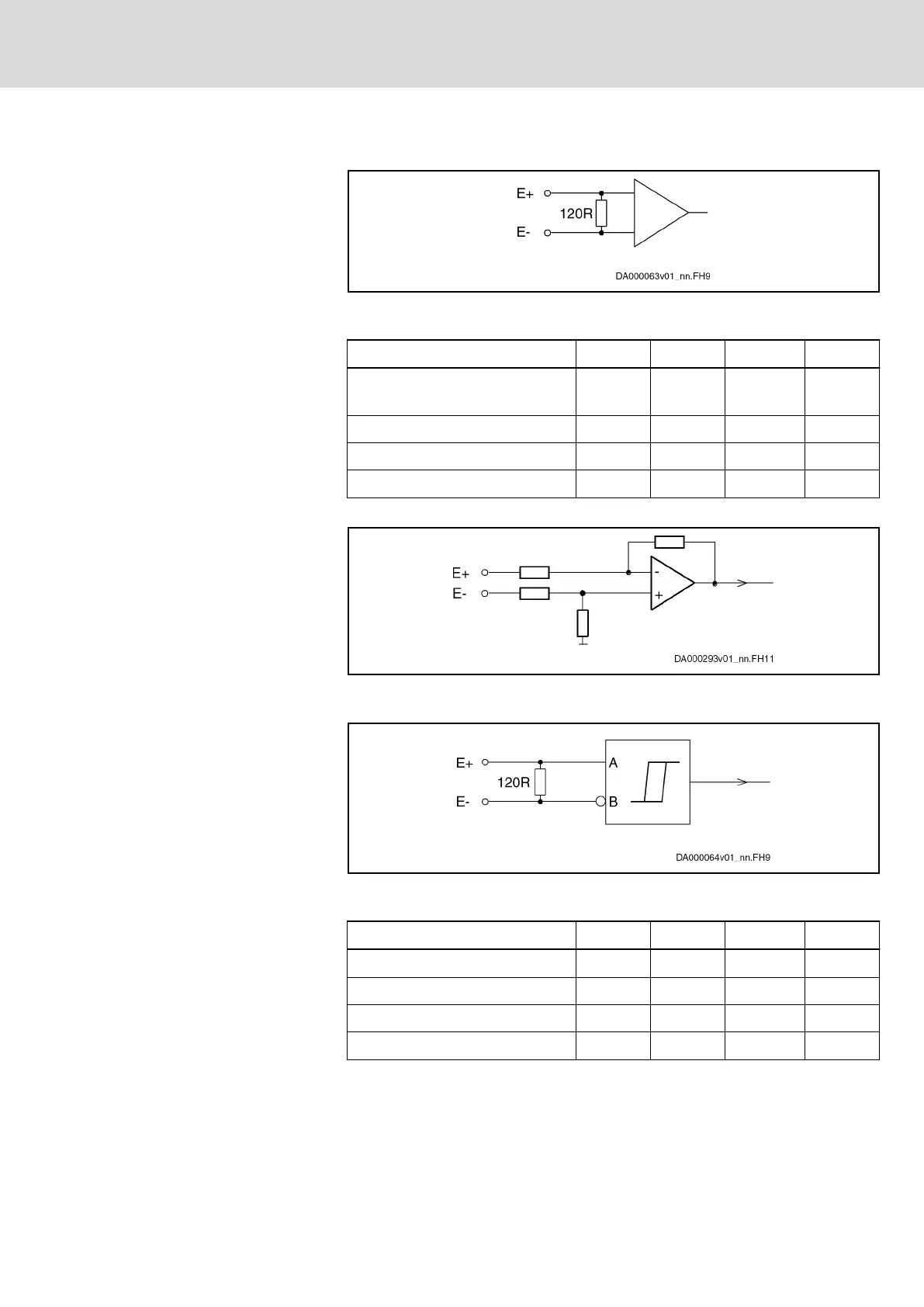
Input circuit for sine signals A+, A-,
B+, B-, R+, R-
Fig. 7-16: Input circuit for sine signals (block diagram)
Properties of differential input for
sine signals
Data Unit min. typ. max.
Amplitude of encoder signal peak-
peak (U
PPencodersignal
)
V
0.8
1.0 1.2
Cut-off frequency (-3 dB) kHz 400
Converter width A/D converter Bit 12
Input resistance ohm 120
Tab. 7-4: Differential input sine
Resolver input circuit for A+, A-, B
+, B-
Fig. 7-17: Input circuit for resolver evaluation (block diagram)
Input circuit for square-wave sig‐
nals
Fig. 7-18: Input circuit for square-wave signals (block diagram)
Properties of differential input for
square-wave signals
Data Unit min. typ. max.
Input voltage "high" V 2.4 5.0
Input voltage "low" V 0 0.8
Input frequency kHz 1000
Input resistance ohm 120
Tab. 7-5: Differential input square-wave signals
DOK-INDRV*-HCS01******-PR05-EN-P Bosch Rexroth AG 199/341
Rexroth IndraDrive CsDrive Systems with HCS01
Technical data of the components

 Loading...


