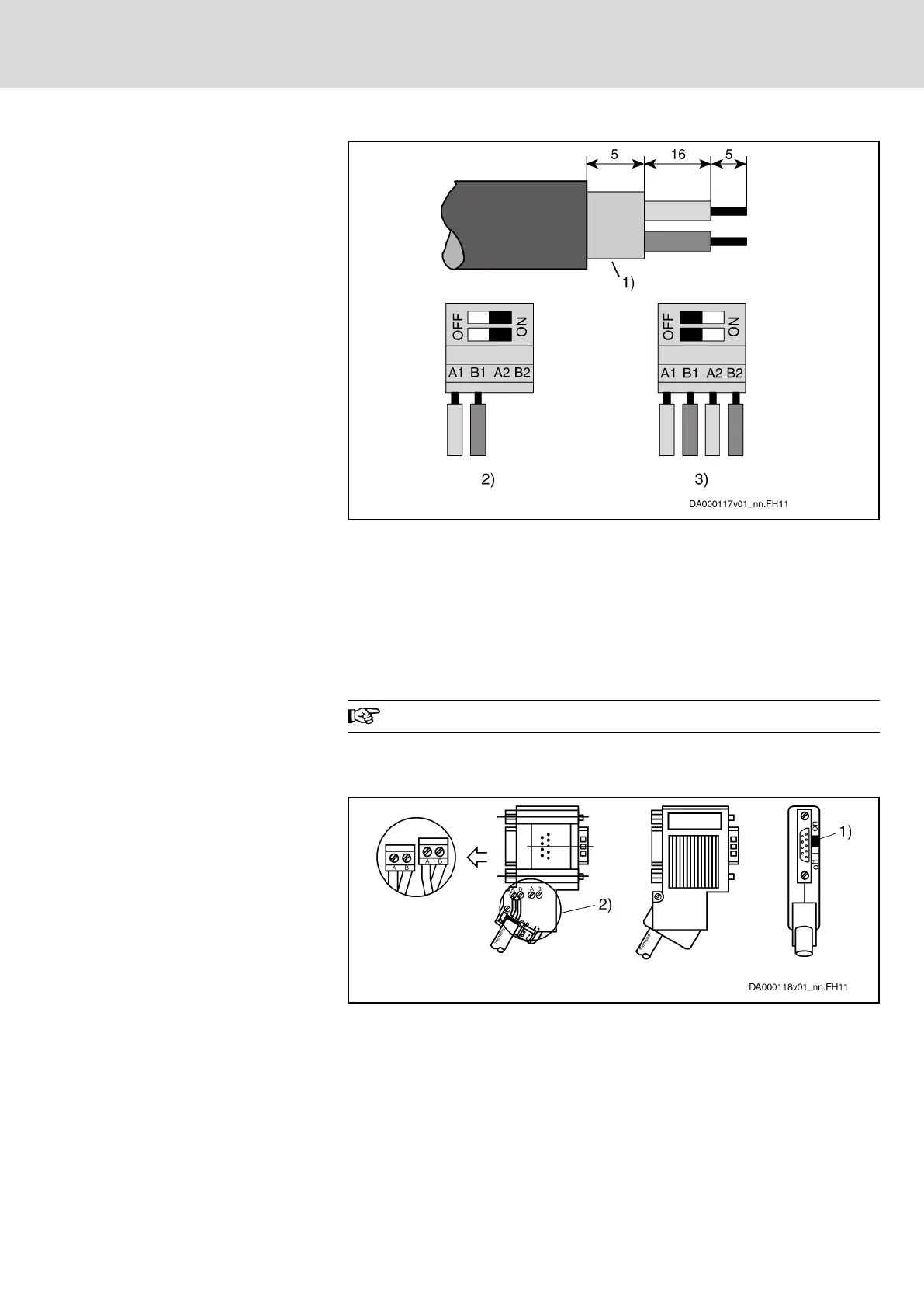
1) Shield
2) Bus connection and switch position for first node and last node
3) Bus connection and switch position for all other nodes
Fig. 6-17: Preparing a Cable for Connecting a Bus Connector
To assemble the bus cable, proceed as follows:
● Use cable according to DIN EN50170 / 2 edition 1996
● Strip cable (see figure above)
● Insert both cores into screw terminal block
Do not interchange the cores for A and B.
● Press cable sheath between both clamps
● Screw on both cores in screw terminals
1) Switch position for first slave and last slave in PROFIBUS-DP
2) Cable shield must have direct contact to metal
Fig. 6-18: Bus Connection for First and Last Slave, Bus Connector With 9-pin
D-Sub Female Connector, INS0541
DOK-INDRV*-HCS01******-PR05-EN-P Bosch Rexroth AG 163/341
Rexroth IndraDrive CsDrive Systems with HCS01
Mounting and installation

 Loading...


