7 Technical data of the components
7.1 Control section
7.1.1 EC - standard encoder evaluation
Supported encoder systems
Supported encoder systems
Encoder systems with a supply voltage of 5 and 12 V:
● MSM motor encoder
● MS2N motor encoder
● MSK motor encoder
● 1V
pp
sin-cos encoder; HIPERFACE®
● 1V
pp
sin-cos encoder; EnDat 2.1; EnDat 2.2
● 1V
pp
sin-cos encoder; with reference track
● 5V TTL square-wave encoder; with reference track
● SSI
● Combined encoder for SSI (combination of SSI and 1V
pp
sin-cos encod‐
er)
● Resolver (resolvers are not supported if optional "Safe Motion" safety
technology is also in use)
● Hall sensor box SHL02.1
● Digital Hall sensor in conjunction with Hall sensor adapter box SHL03.1
Encoder type
IndraDyn S MSM motors (5V supply voltage)
Properties
Encoder systems of the MSM motors are digital encoder systems that can be
evaluated in absolute form.
The optionally available battery box (SUP-E0x-MSM-BATTERYBOX) facili‐
tates the multi-turn functionality.
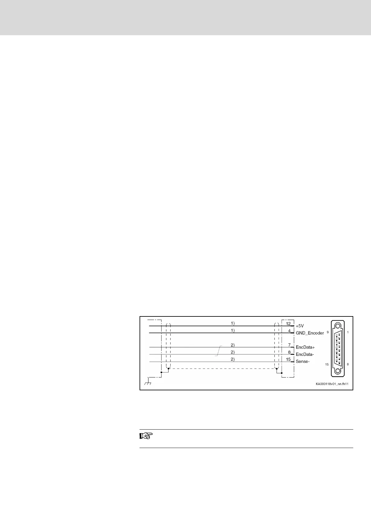
Connection diagram
1) Line cross section ≥ 0.5 mm²; observe allowed encoder cable
length
2) Line cross section ≥ 0.14 mm²
Fig. 7-1: EC connection diagram with encoder system of IndraDyn S MSM
motors
For direct connection to the encoder system, use our RKG0033 or
RKG0062 cable.
Power supply
5 V (the voltage is made available via the EC interface)
DOK-INDRV*-HCS01******-PR05-EN-P Bosch Rexroth AG 181/341
Rexroth IndraDrive CsDrive Systems with HCS01
Technical data of the components

 Loading...


