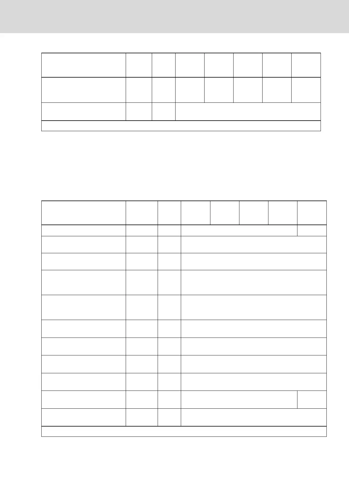
Description Symbol Unit
HCS01.1E
-W0003-
_-02
HCS01.1E
-W0006-
_-02
HCS01.1E
-W0009-
_-02
HCS01.1E
-W0013-
_-02
HCS01.1E
-W0018-
_-02
Continuous output current when
f
s
= 16 kHz; output frequency
f
out
< f
out_still
8)
I
out_cont0Hz
_16
A 0.4 0.7 0.9 1.3 4.2
Assigned output filters at nom. da‐
ta; f
s
= 4 kHz
tbd
Last modification: 2015-06-12
1) Also depending on firmware and control section; see parame‐
ter description "P-0-0001, Switching frequency of power output
stage"; see "P-0-4058, Amplifier type data"
2) 3) Guide value, see following note
4) See following note regarding output current reduction
5) 6) 7) 8) See parameter description "P-0-0556, Config word of axis con‐
troller", load-dependent reduction of switching frequency fs
Tab. 7-48: HCS - Power section data - inverter
Power section data - inverter
Description Symbol Unit
HCS01.1E
-W0005-
_-03
HCS01.1E
-W0008-
_-03
HCS01.1E
-W0018-
_-03
HCS01.1E
-W0028-
_-03
HCS01.1E
-W0054-
_-03
Allowed switching frequencies
1)
f
s
kHz 4, 8, 12, 16 4, 8, 12
Output voltage, fundamental wave
for V/Hz (U/f) control
V
out_eff
V ~UDC x 0.71
Output voltage, fundamental wave
for closed-loop operation
V
out_eff
V ~UDC x 0.71
Rise of voltage at output with
U
LN_nenn
and 15 m motor cable
length phase-phase (10-90%)
2)
dv/dt kV/µs 5.00
Rise of voltage at output with
U
LN_nenn
and 15 m motor cable
length phase-ground (10-90%)
3)
dv/dt kV/µs 5.00
Output frequency range when
f
s
= 2 kHz
f
out_2k
Hz -
Output frequency range when
f
s
= 4 kHz
f
out_4k
Hz 0...400
Output frequency range when
f
s
= 8 kHz
f
out_8k
Hz 0...800
Output frequency range when
f
s
= 12 kHz
f
out_12k
Hz 0...1200
Output frequency range when
f
s
= 16 kHz
f
out_16k
Hz 0...1600 -
Output frequency threshold for de‐
tecting motor standstill
4)
f
out_still
Hz 4
Last modification: 2015-06-12
DOK-INDRV*-HCS01******-PR05-EN-P Bosch Rexroth AG 245/341
Rexroth IndraDrive CsDrive Systems with HCS01
Technical data of the components

 Loading...


