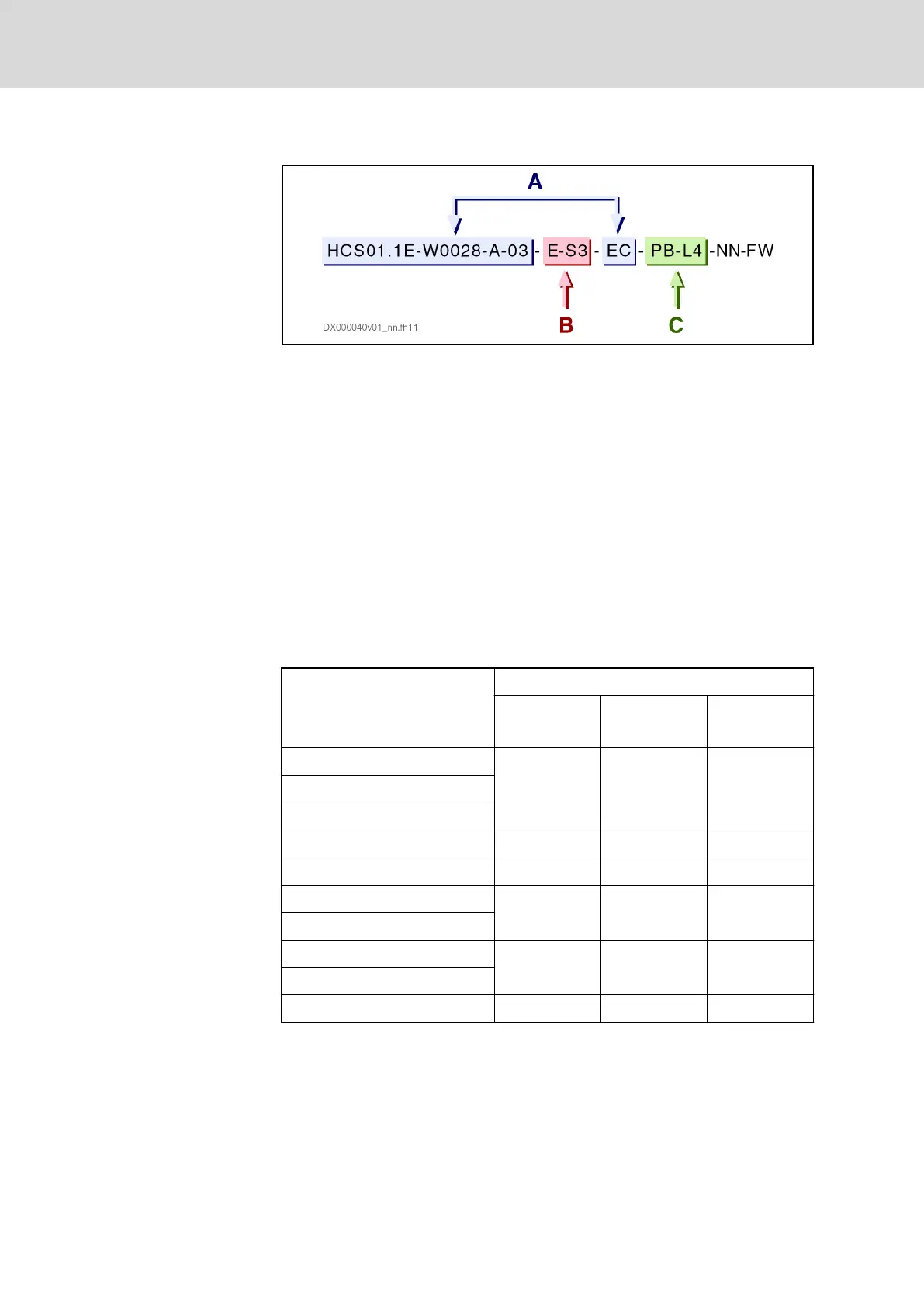
Type code example:
A Basic device (maximum current [W0028 = 28 A], series [03],
on-board connection point [EC])
B Control section design (E = Economy; S3 = sercos III)
C Optional connection points (PB = ProfiBus; L4 = safety technol‐
ogy [STO, SBC])
Fig. 4-13: Type code HCS01
The tables below contain the individual power values required by the drive
controller. The power requirement of the supplying 24 V power supply unit re‐
sults from the sum of these individual power values.
Basic device power requirements
The power requirements of the basic device result from
● Maximum current of drive controller
● Control section design
Table 1: Basic device power requirements
Maximum current, series
1)
HCS01.1E-…
Control section design
E-S3
(ECONOMY)
B-ET
(BASIC)
A-CC
(ADVANCED)
W0003-A-02-x-xx-EC 8.1 W 12.7 W 13.4 W
W0006-A-02-x-xx-EC
W0009-A-02-x-xx-EC
W0013-A-02-x-xx-EC 9.4 W 14.3 W 15 W
W0018-A-02-x-xx-EC 12.7 W 17.3 W 18 W
W0005-A-03-x-xx-EC 9.4 W 14.3 W 15 W
W0008-A-03-x-xx-EC
W0018-A-03-x-xx-EC 12.7 W 17.3 W 18 W
W0028-A-03-x-xx-EC
W0054-A-03-x-xx-EC 25.7 W 30.3 W 31 W
1)
The wild card x-xx in this column represents the control section
design. Example: The basic device HCS01.1E-W0028-A-03-E-
S3-EC has a power requirement of 12.7 W.
Tab. 4-21: Basic device power requirements
Power requirements of the option‐
al connection points
If the drive controller has optional connection points, the power requirements
of the basic device are increased.
Bosch Rexroth AG DOK-INDRV*-HCS01******-PR05-EN-P70/341
Rexroth IndraDrive CsDrive Systems with HCS01
Combining the individual components

 Loading...


