3-114
Confidential
Assembling Notes:
• When connecting the main drain tube and air vent tube to the ink absorber box, take care not
to connect them at an angle. Tubes connected at an angle come off easily, resulting in ink
leakage. After connection, check that there is no ink leakage.
• When putting the ink absorber box into the lower cover, route the main drain tube and air
vent tube through the cutout in the boss provided on the lower cover (see the previous page).
• If you replace the ink absorber box (without replacing the main PCB), reset the purge count,
using the procedure given in Chapter 4, Section 4.4.
It is also recommended that the flushing box be replaced (Section 3.9.17 in this chapter) and
the flushing count be reset as necessary since the flushing count may approach the upper
limit.
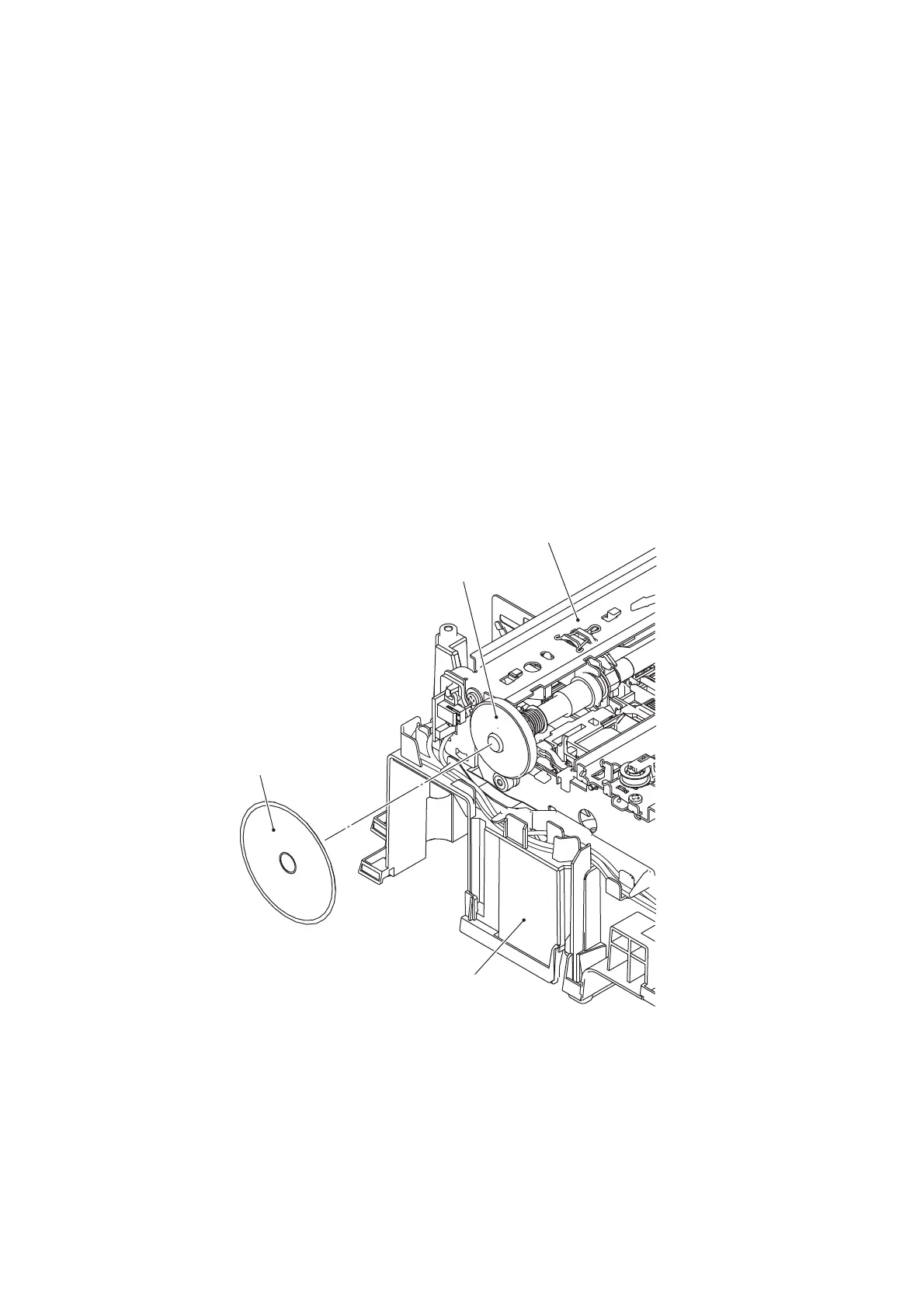
(5) Peel off the PF encoder disk from the PF roller gear L only when it should be replaced.
Note: Once removed, the PF encoder disk will become unusable and a new disk will have
to be put back in.
Note: Remove any adhesive remaining left on the PF roller gear L.
Assembling Note: When attaching the PF encoder disk to the PF roller gear L, using a spatular
tool makes the job easier. Put on clean gloves to protect the disk surface from dust or
fingerprints.
(3_083)
CR guide rail
PF roller gear L
PF encoder disk
Lower cover
 Loading...