3-95
Confidential
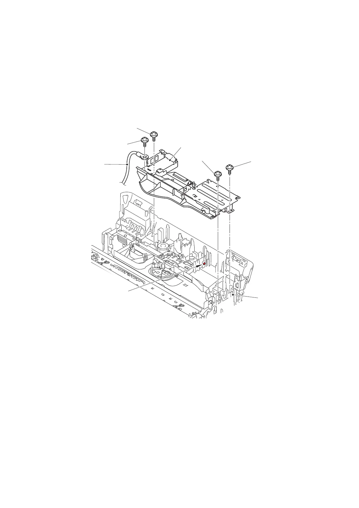
9.43 Power Supply PCB ASSY
(1) Release the wiring of the Switchback sensor harness and PF encoder/registration
sensor harness.
(2) Remove the one screw (TAPTITE CUP S M3x6) to release the Engine FG wire
from the Main PCB frame.
(3) Remove the one screw (TAPTITE CUP S M3x6) and two screws (TAPTITE CUP B
M3x10) from the Main PCB frame.
(4) Release the Hook on the Lower cover and remove the Main PCB frame.
Fig. 3-110
TAPTITE CUP S M3x6
TAPTITE CUP B M3x10
Main PCB frame
Hook
Engine FG wire
Lower cover
TAPTITE CUP S M3x6
TAPTITE CUP B M3x10
<Front>
<Rear>
 Loading...