BRP-Rotax
INSTALLATION MANUAL
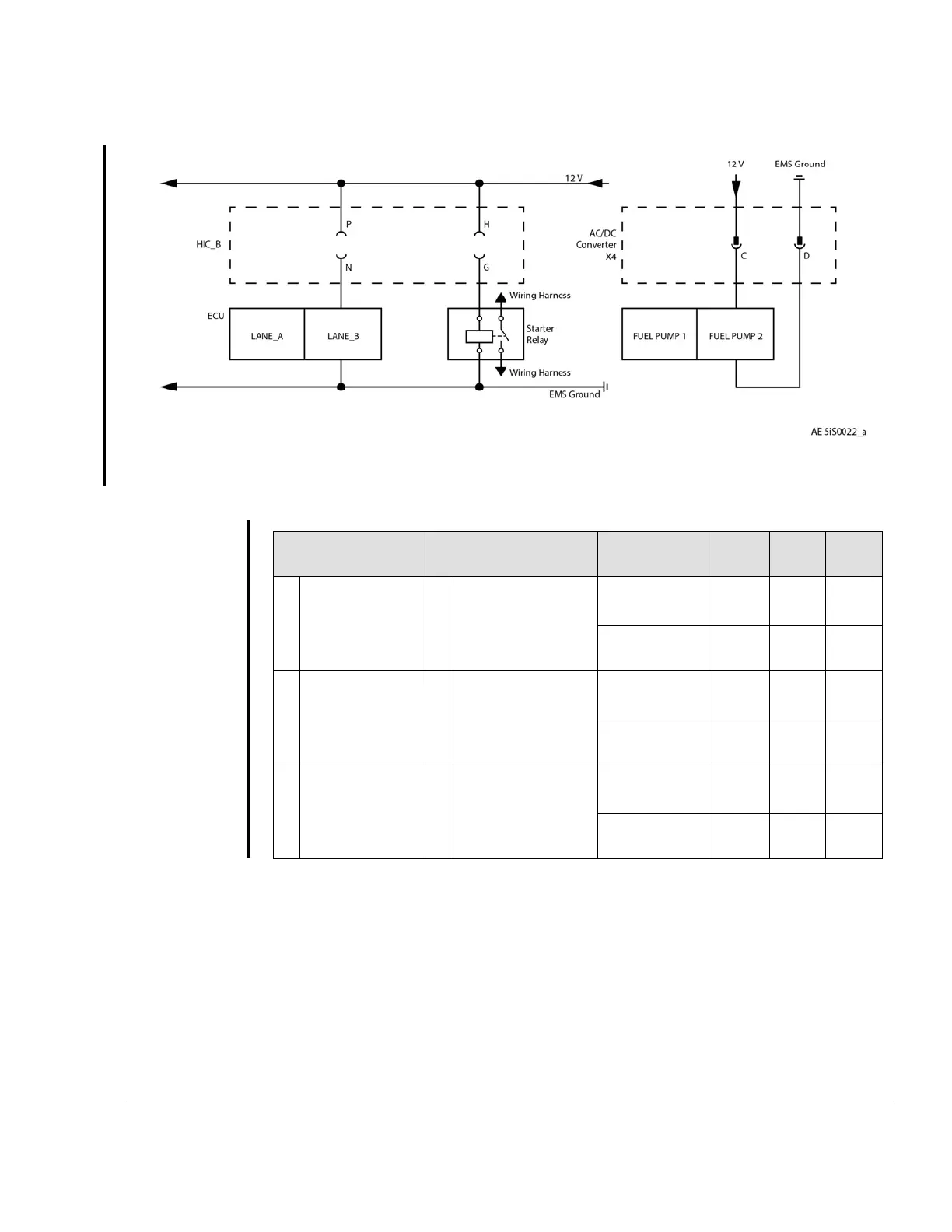
Figure 9.12: HIC B Connector – Engine controls
Terminal (Supply) Terminal (Ground) Interface
Parameter
Min. Max. Nom-
inal
P
LANE_SEL_
SW_B_1
N
LANE_SEL_SW_
B_2
Nominal
Voltage
12 V
Nominal
Current
7.5 A
F
SUPP_START_
SWITCH
E
CONN_START-
ER_REL_SW
Nominal
Voltage
12 V
Nominal
Current
5 A
c
SIG_FUEL_
PUMP_2
D
GND_FUEL_
PUMP_2
Nominal
Voltage
12 V
Nominal
Current
10 A
The HIC B connector allows powering ECU Lane B. Interfaces to indication elements are
described in Chapter 77-00-00.
X1, X2 Connector See Chapter 24-00-00 section Interface Description.
Regulator A See Chapter 24-00-00 section 24–00–00 section Interface Description.
Wiring
harness
grounding
The grounding cable must be attached to Fusebox Regulator A. See Chapter 24-00-00
section Fusebox Regulator A
Effectivity: 916 i A / C24
Edition 0/Rev. 1
76–00–00
Page 13
December 01 2023

 Loading...


