BRP-Rotax
INSTALLATION MANUAL
Separation of
EMS and Air-
frame circuit
916 i TYPE C24
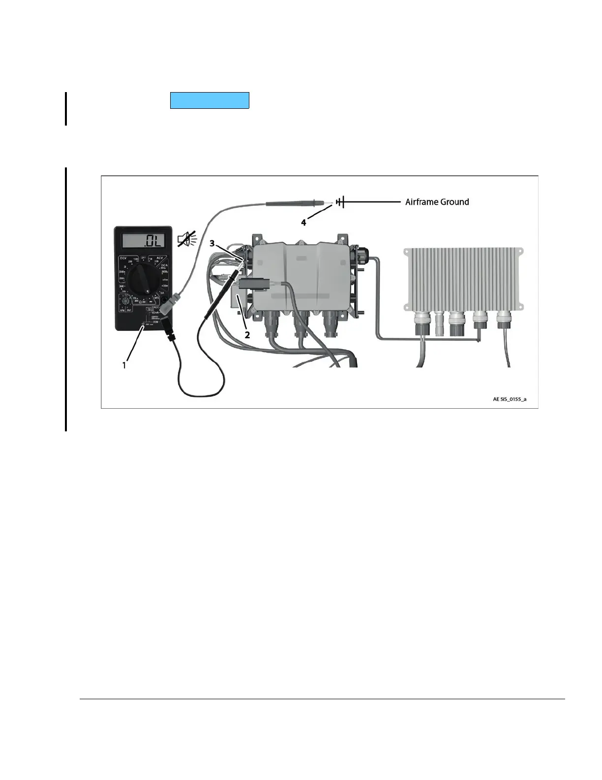
Test to ensure there is no continuity between Fusebox Regulator A and Fusebox Regula-
tor B in static condition (Fusebox is not supplied with power by an external power source).
To determine the ECU BUS voltage at the transient moment of the engine start an oscillo-
scope must be used and also the total consumption of all electrical loads needs to be
checked.
Figure 3.25: Validation of EMS and Airframe Circuit separation
1 Multimeter 2
Rectifier regulator A (black connector)
3
Ground connections regulator A
4
Airframe ground
In case of continuity the installation is not sufficient and the wiring concept needs to be
revised.
Effectivity: 916 i A / C24
Edition 0/Rev. 1
24–00–00
Page 29
December 01 2023

 Loading...


