BRP-Rotax
INSTALLATION MANUAL
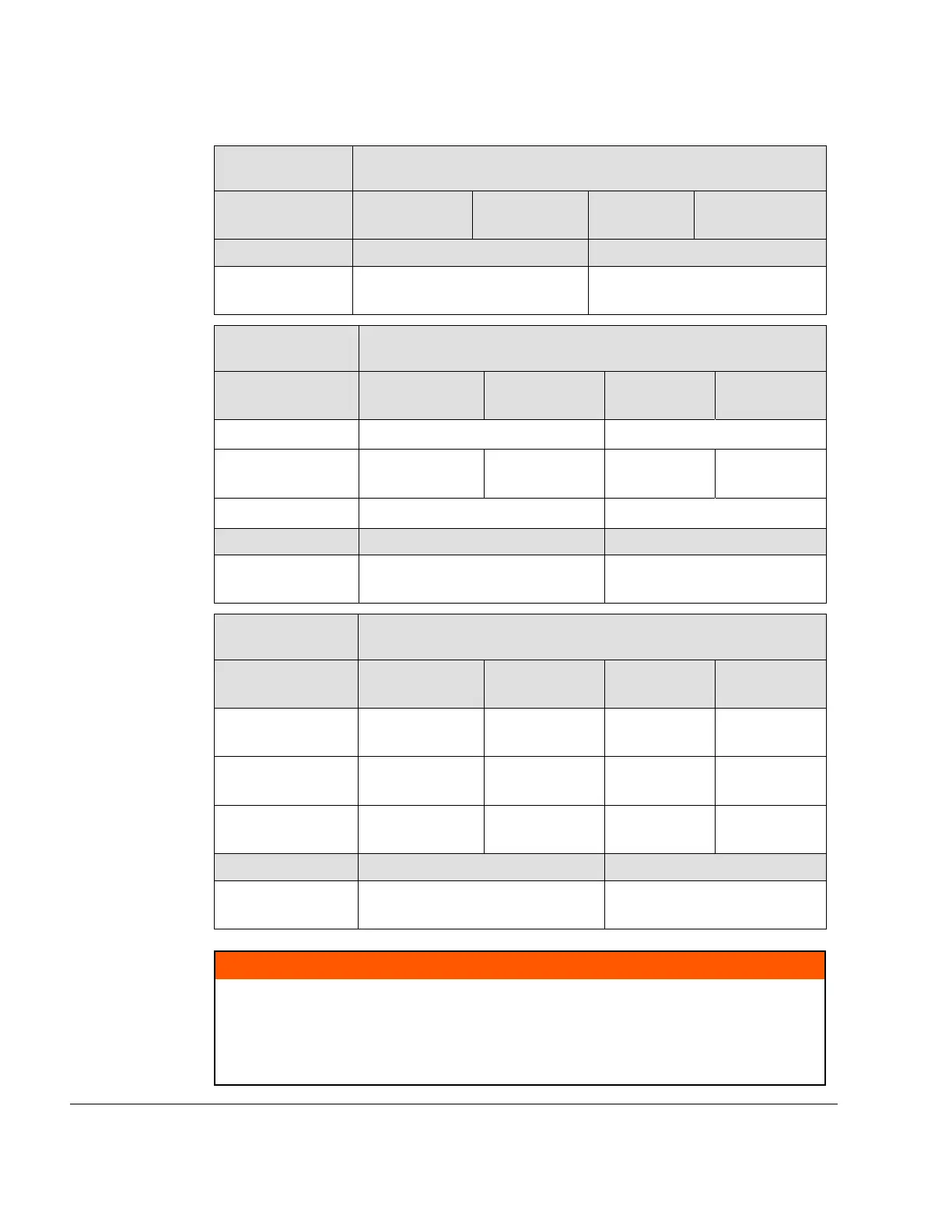
Interface
Parameter
Value
Attachment
points
L1 R1 L2 R2
Thread M10
—
Max. usable
Thread length
25 mm (0.98 in.)
Interface
Parameter
Value
Attachment
points
L3 R3 L4 R4
x-axis (in) - 615 mm (-24.21 in.) - 181 mm (-7.13 in.)
y-axis (in)
105 mm (4.13
in.)
-105 mm (-4.13
in.)
90 mm (3.54
in.)
-90 mm
(-3.54 in.)
z-axis (in) -7 mm (-0.28 in.) 12.2 mm (0.48 in.)
Thread
—
M10
Max. usable
Thread length
16 mm (0.63 in.)
Interface
Parameter
Value
Attachment
points
L5 R5 L6 R6
x-axis (in)
- 51 mm (-1.97
in.)
- 71 mm (-2.79
in.)
- 51 mm
(-1.97 in.)
- 71 mm
(-2.79 in.)
y-axis (in)
48 mm (1.89
in.)
-64.5 mm
(-2.54 in.)
48 mm (1.89
in.)
-64.5 mm
(-2.54 in.)
z-axis (in)
25.4 mm (1.00
in.)
39 mm (1.53
in.)
-25.4 mm
(-1.00 in.)
-39 mm
(-1.53 in.)
Thread M8 M8
Max. usable
Thread length
20 mm (0.79 in.) 20 mm (0.79 in.)
m WARNING
Non-compliance can result in serious injuries or death!
The aircraft or fuselage manufacturer must design the engine suspension so that it can
safely carry the maximum occurring operational loads without exceeding the max. al-
lowable forces and bending moments on the engine housing and attachment points.
Tighten all engine suspension screws as specified by the aircraft manufacturer.
72–00–00
Page 10
December 01 2023
Effectivity: 916 i A / C24
Edition 0/Rev. 1

 Loading...


