3-32 2007 Buell Lightning: Engine
HOME
8. Rotate engine down and install exhaust header only and
tighten fasteners to 72-96 in-lbs (8.1-10.8 Nm).
NOTES
● Exhaust header must be torqued with the engine rotated
in the down position. It is not possible to reach fasteners
on the rear exhaust at the head with engine rotated in the
up position.
● It is necessary to tighten the front head pipe first.
● Tighten header nuts gradually, alternating between studs
to insure that exhaust rings are flush with engine.
9. When the exhaust header has been torqued, rotate
engine back up into frame.
NOTE
When tightening front isolator bolt it is important to keep load
off of isolator bolt for installation purposes. Alternate between
tightening front isolator bolt and raising engine with scissors
jack.
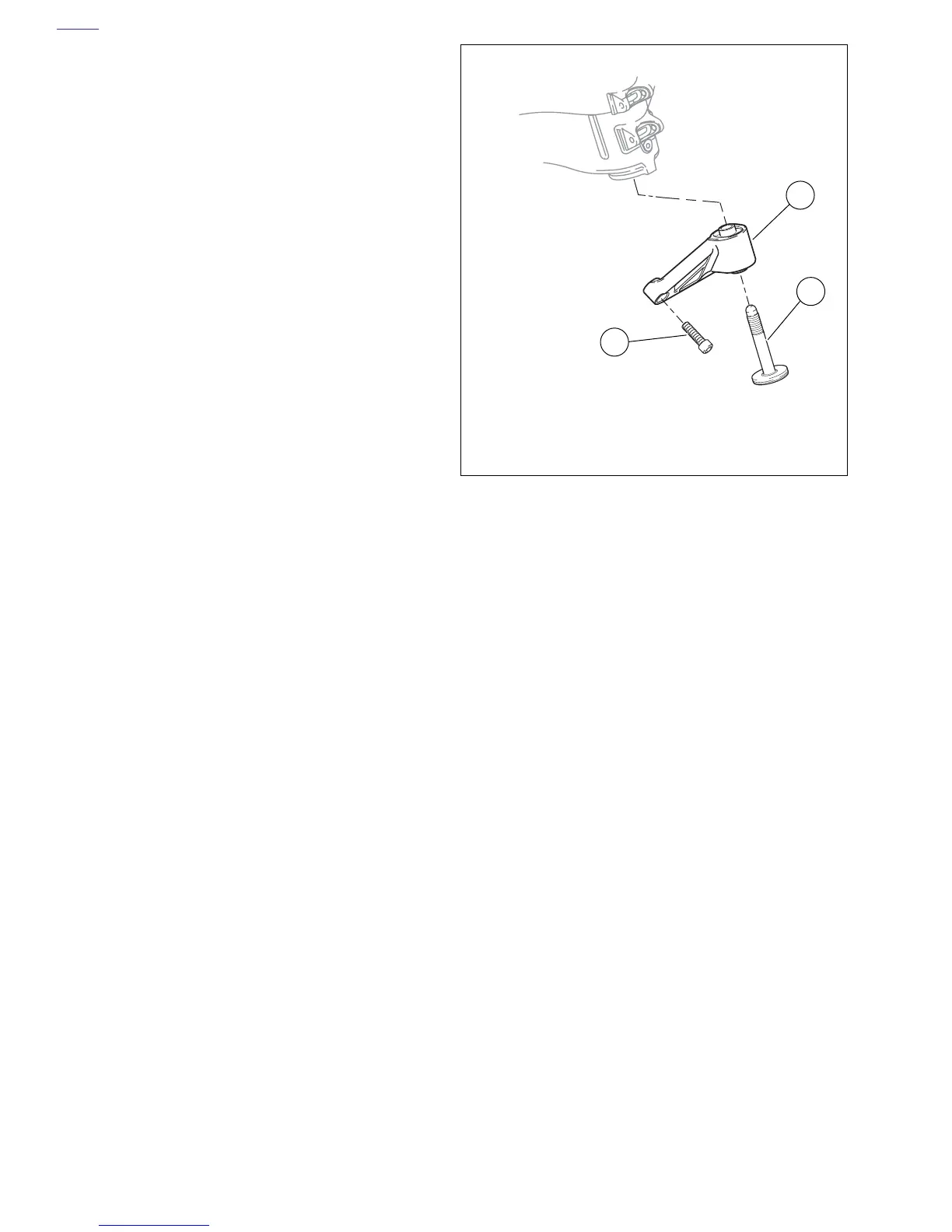
10. See Figure 3-43. Insert front isolator bolt (3) through
front isolator (1) and loosely thread into frame. Do not
tighten at this point.
11. Install isolator mounting fasteners (2) and tighten to 49-
51 ft-lbs (66.4-69.1 Nm).
12. See Figure 3-42. Tighten front isolator bolt to 49-51 ft-lbs
(66-69 Nm).
13. Tighten rear isolator bolt to Rear 25-27 ft-lbs (33.9-36.6
Nm).
14. Install rear tie bar to frame and tighten to 25-27 ft-lbs
(33.9-36.6 Nm).
15. Install center tie bar to engine and tighten to 25-27 ft-lbs
(33.9-36.6 Nm).
NOTE
When reinstalling the tie bar, first mount to engine and then to
“V” bracket in order to prevent damage to threaded area of
crankcase.
16. Install front tie-bar and clutch cable lower retaining clamp
to engine and tighten to 25-27 ft-lbs (33.9-36.6 Nm).
17. Install front “V” bracket with oil cooler to main frame.
a. Install “V” bracket to main frame from the left side of
the vehicle and tighten to 120-144 in-lbs (13.6-16.3
Nm).
b. Install front tie-bar to “V” bracket and tighten to 25-
27 ft-lbs (33.9-36.6 Nm).
c. Attach remote idle adjustment cable “V” to bracket
using nylon cable straps.
d. Attach regulator wiring harness to clutch cable
below clutch cable lower retaining clamp using a
nylon cable strap.
18. Remove scissors jack.
Figure 3-43. Front Isolator
b1049x3x
1. Front isolator
2. Front isolator fasteners (2)
3. Front isolator bolt
1
3
2