2007 Buell Lightning: Fuel System 4-121
HOME
INSTALLATION
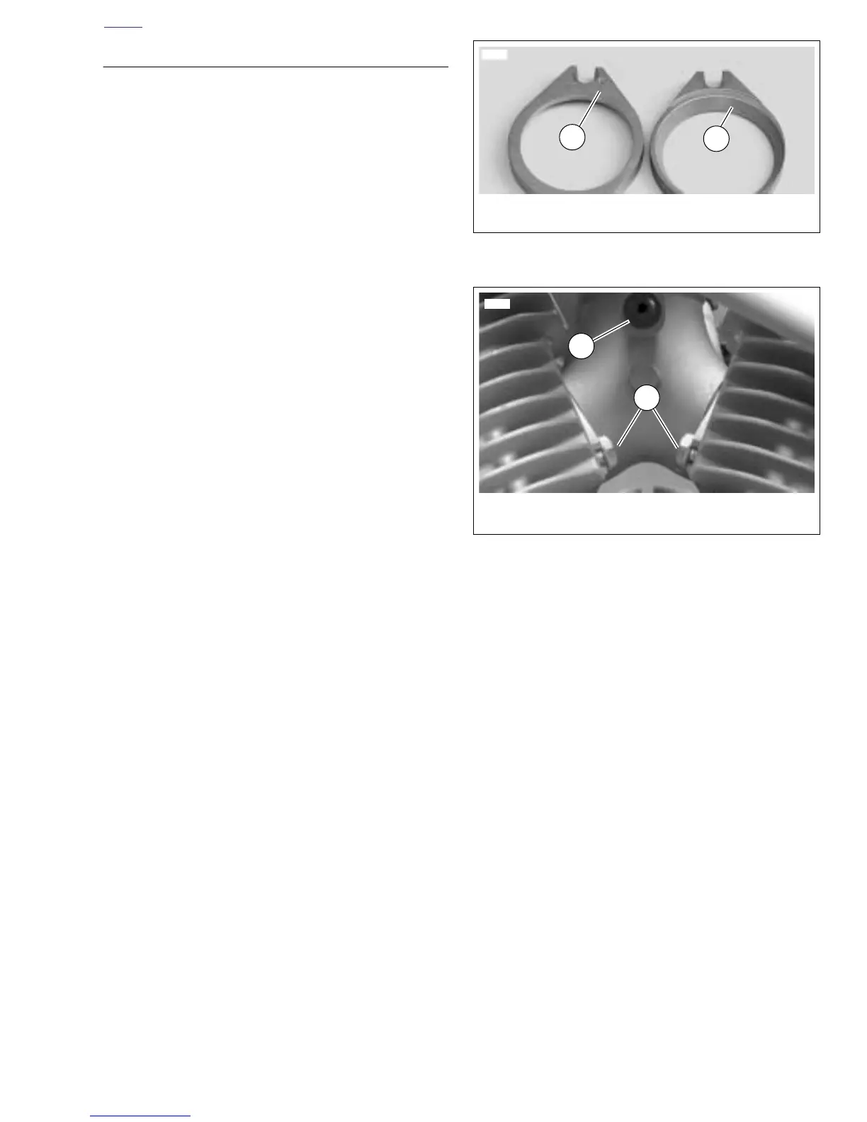
1. See Figure 4-111. Install front and rear intake flanges
onto throttle body with the counterbore facing out. Each
intake flange is labeled and the pieces are not inter-
changeable.
2. Place a new seal in each intake flange with the beveled
side against the counterbore.
3. Install throttle body/intake manifold assembly.
a. See Figure 4-112. Slide the assembly toward
installed position. Manifold should slide over fasten-
ers (2) on primary cover side of engine.
b. Align holes in intake flanges with those in cylinder
heads and start screws.
c. Make sure throttle body is centered between cylin-
ders and tighten all intake flange screws to 96-120
in-lbs (10.8-13.6 Nm).
4. See Figure 4-112. Install fastener holding manifold to cyl-
inder brace and tighten to 90-120 in-lbs (10-13.6 Nm).
5. Attach throttle cables. See 2.24 THROTTLE CONTROL.
6. Attach wiring.
a. Injector cables are tagged F(ront) and R(ear) for
ease of assembly. Push connector halves together
until latches “click.” Grooves in female connector
must align with the tabs in male housing.
b. Connect throttle position sensor by pushing the con-
nector halves together. Slots on female connector
must fully engage tabs on male connector housing.
7. Connect fuel line and EVAP hose to port at bottom of
throttle body (California models only).
8. Secure idle adjuster cable to "V" bracket with a cable
strap.
9. Calibrate throttle position sensor if removed or replaced.
See 1.19 THROTTLE POSITION SENSOR (TPS).
10. Install coil. 4.32 IGNITION COIL
11. Install air cleaner cover. See 4.44 AIR CLEANER
ASSEMBLY.
12. Check throttle cable adjustment. See 2.24 THROTTLE
CONTROL.
13. Install air scoops. See 2.39 AIR SCOOPS.
14. Verify engine speed. See 1.19 THROTTLE POSITION
SENSOR (TPS).
Figure 4-111. Intake Flanges
Figure 4-112. Intake Manifold (primary side)
1
2
1. Label (F=front intake)
2. Counterbore
6954
1. Manifold to cylinder brace fastener
2. Intake flange fastener (2)
2
1
8750a