7-78 2007 Buell Lightning: Electrical
HOME
REMOVAL
1. Remove sprocket cover. See 2.34 SPROCKET COVER.
2. See Figure 7-98. Disconnect appropriate connector(s).
INSTALLATION
NOTES
● See Figure 7-99. Convolute covering the return oil line
should have the seam rotated to the back side of the oil
line away from wiring.
● If oil fitting cover was removed, install at this time.
1. Route the vehicle speed sensor wiring behind the starter
trigger wire.
2. See Figure 7-98. Route stator wiring, main harness,
vehicle speed sensor wiring, and actuator cable (XB12
models only) behind the vent line fitting (6) and to the
right side of the sprocket cover boss (3).
3. See Figure 7-98. Route oil pressure switch wiring (9)
from main harness (5), to oil pressure switch located on
front of engine and connect to the oil pressure switch.
4. Route the regulator wiring bundle over oil pressure
switch wiring back to the sprocket cover area.
5. See Figure 7-98. Connect the (4 pin) stator connector (8)
and position as shown.
6. Connect the (2-pin) voltage regulator (1).
7. See Figure 7-98. Position the voltage regulator connec-
tor (1) as it is shown, with the connector latch to the back
and above the bottom sprocket cover boss.
NOTE
Make sure that the voltage regulator connector is all the way
back against the plastic wire guard.
8. See Figure 7-101. At the oil pressure switch, use a cable
strap to encircle the voltage regulator wire bundle and
the oil pressure switch wire, and secure to the base of
the oil pressure switch itself.
9. Then move back and cable strap that bundle with the
cam position sensor wires. Orient the cam sensor wires
in front and the oil pressure switch wire behind the volt-
age regulator bundle.
10. See Figure 7-100. Connect the neutral safety switch (sin-
gle bullet), and the cam position sensor (3-pin black).
11. See Figure 7-100. Using a cable strap, secure the loop of
the neutral safety wire to the cam position connector (13)
under the attachment clip on the connector.
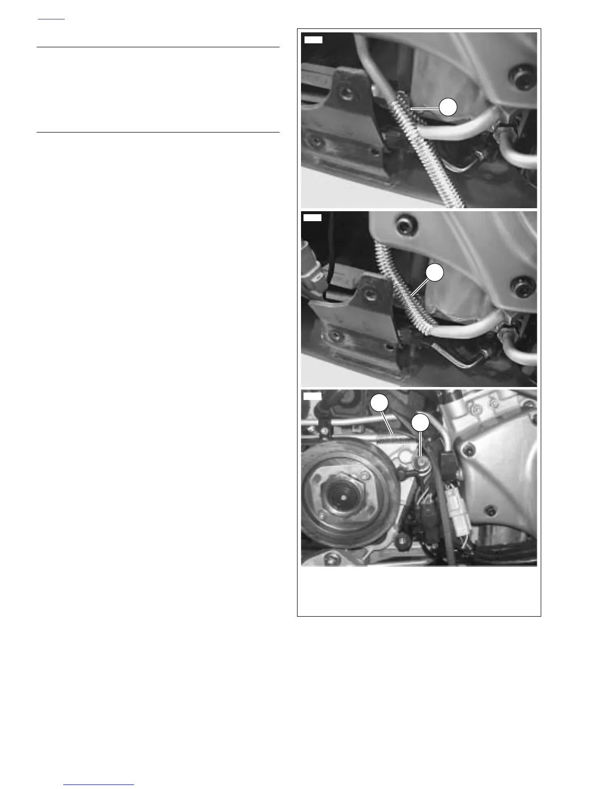
Figure 7-99. Convoluted Covering for Oil Return Line
12008
12009
12367
1. Reflective convolute covering with seam
2. Covering in place on bottom of return line
3. Covering in place on top of return line
4. Sprocket cover boss
3
1
2
4