2007 Buell Lightning: Electrical 7-79
HOME
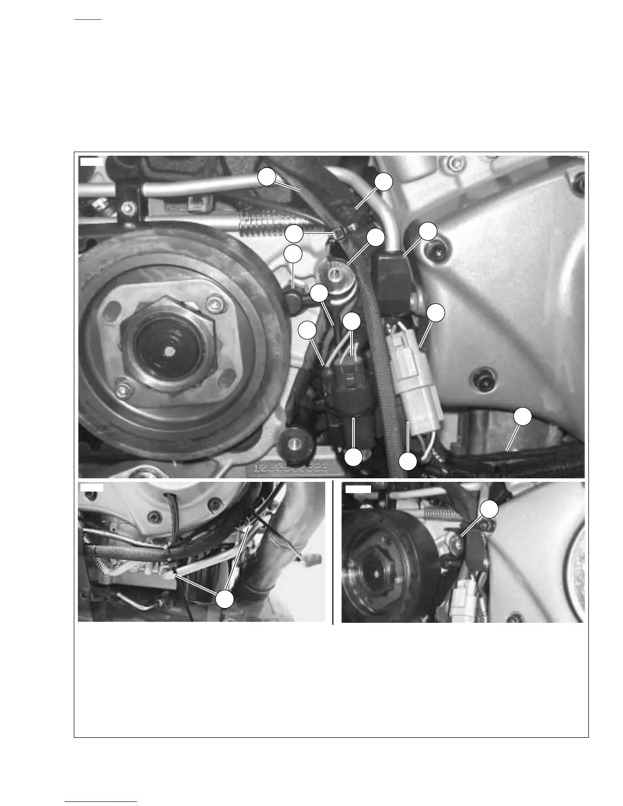
12. See Figure 7-101. Position the cam position sensor wire
bundle, voltage regulator wire bundle and the oil pres-
sure switch wiring inboard then push the wire bundle up
against the return oil line and cable strap them to the
return oil line.
13. See Figure 7-103. Capture the main wire harness bun-
dle, the vehicle speed sensor lead, the stator bundle, and
the muffler actuator cable (if applicable) to the oil return
line with a cable strap.
14. Connect the vehicle speed sensor last.
NOTE
The vehicle speed sensor is positioned below the vent line fit-
ting in order for the front sprocket cover to conform to the
additional components.
15. Install sprocket cover. See 2.34 SPROCKET COVER.
Figure 7-100. Sprocket Cover Wiring and Connections
1. Stator connector [46]
2. Oil pressure switch wiring
3. Vehicle speed sensor connector [65]
4. Gear cover vent line with cover (to protect wiring)
5. Extended wire guard to protect wiring
6. Main harness
7. Interactive exhaust cable
8. Cable wrap securing Interactive exhaust cable and
main harness to oil return line
9. Location of neutral switch
10. Voltage regulator connector [77], behind cam posi-
tion sensor (is also part of the bundle secured to
the cam position sensor with a cable strap)
11. Cam position sensor connector [14]
12. Neutral safety switch (single bullet) [131]
13. Cable strap securing neutral connector to cam
position sensor connector [14]
14. Position of forward cable straps to secure wiring
11
1
3
9
7
4
6
10
8
2
14
13
12370
12012a
12369a
5
12
5