Section 7. Installation
261
Example PRT specifications:
• Alpha = 0.00385 (PRTType 1)
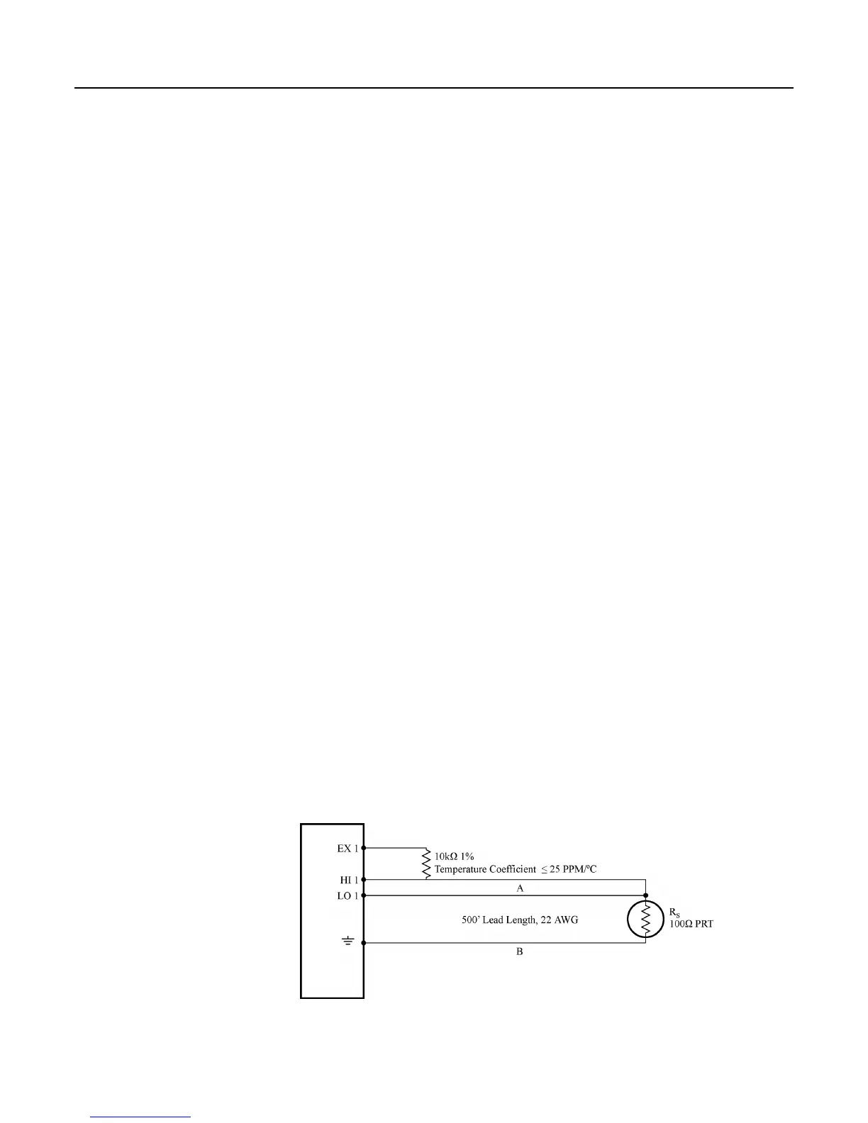
The temperature measurement requirements in this example are the same as in
PT100 in Four-Wire Half-Bridge
(p. 258). In this case, a three-wire half-bridge and
CRBasic instruction BRHalf3W() are used to measure the resistance of the PRT.
The diagram of the PRT circuit is shown in figure PT100 in Three-Wire Half-
Bridge
(p. 261).
As in section PT100 in Four-Wire Half-Bridge (p. 258), the excitation voltage is
calculated to be the maximum possible, yet allow the measurement to be made on
the ±25-mV input range. The 10-kΩ resistor has a tolerance of ±1%; thus, the
lowest resistance to expect from it is 9.9 kΩ. Solve for V
X
(the maximum
excitation voltage) to keep the voltage drop across the PRT less than 25 mV:
0.025 V > (V
X
* 115.54)/(9900+115.54)
V
X
< 2.16 V
The excitation voltage used is 2.2 V.
The multiplier used in BRHalf3W() is determined in the same manner as in
PT100 in Four-Wire Half-Bridge
(p. 258). In this example, the multiplier (R
f
/R
0
) is
assumed to be 100.93.
The three-wire half-bridge compensates for lead wire resistance by assuming that
the resistance of wire A is the same as the resistance of wire B. The maximum
difference expected in wire resistance is 2%, but is more likely to be on the order
of 1%. The resistance of R
S
calculated with BRHalf3W() is actually R
S
plus the
difference in resistance of wires A and B. The average resistance of 22-AWG
wire is 16.5 ohms per 1000 feet, which would give each 500-foot lead wire a
nominal resistance of 8.3 ohms. Two percent of 8.3 ohms is 0.17 ohms.
Assuming that the greater resistance is in wire B, the resistance measured for the
PRT (R
0
= 100 ohms) in the ice bath would be 100.17 ohms, and the resistance at
40°C would be 115.71. The measured ratio R
S
/R
0
is 1.1551; the actual ratio is
115.54/100 = 1.1554. The temperature computed by PRTCalc() from the
measured ratio will be about 0.1°C lower than the actual temperature of the PRT.
This source of error does not exist in the example in PT100 in Four-Wire Half-
Bridge
(p. 258) because a four-wire half-bridge is used to measure PRT resistance.
A terminal input module can be used to complete the circuit in figure PT100 in
Three-Wire Half-Bridge
(p. 261). Refer to the appendix Signal Conditioners (p. 539)
for information concerning available TIM modules.
Figure 80: PT100 in three-wire half-bridge