Section 4. Quickstart Tutorial
40
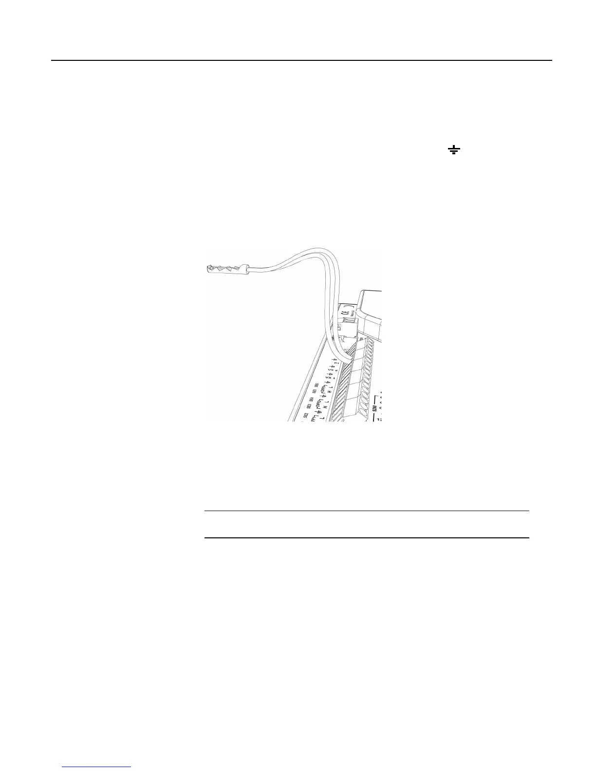
4.1.3.3.3 Pulse Sensor Wiring
Wiring a pulse sensor to a CR800 is straight forward, as shown in figure Pulse-
Input Wiring -- Anemometer Switch
(p. 40). Pulse sensors have two active wires,
one of which is always ground. Connect the ground wire to a
(ground)
channel. Connect the other wire to a pulse channel. Sometimes the sensor will
require power from the CR800, so there will be two more wires – one of which is
always ground. Connect power ground to a G channel. Do not confuse the pulse
wire with the positive power wire, or damage to the sensor or CR800 may result.
Some switch-closure sensors may require a pull-up resistor. Consult figure
Connecting Switch Closures to Digital I/O
(p. 303) for information on use of pull-up
resistors.
Figure 8: Pulse-input wiring -- anemometer switch
4.1.3.4 RS-232 Sensors
The CR800 has 4 ports available for RS-232 input as shown in figure Location of
RS-232 Ports
(p. 41).
Note With the correct adaptor, the CS I/O port can be used as an RS-232 I/O
port.
As indicated in figure Use of RS-232 and Digital I/O when Reading RS-232
Devices
(p. 41), RS-232 sensors can be connected to the RS-232 port or to digital
I/O port pairs. Ports can be set up with various baud rates, parity options, stop-bit
options, and so forth as defined in CRBasic Editor Help.

 Loading...