Section 8. Operation
296
8.1.3.3 Strain Calculations
Read More! The FieldCalStrain() Demonstration Program (p. 154) section has
more information on strain calculations.
A principal use of the four-wire full bridge is the measurement of strain gages in
structural stress analysis. StrainCalc() calculates microstrain, με, from an
appropriate formula for the particular strain bridge configuration used. All strain
gages supported by StrainCalc() use the full-bridge schematic. In strain-gage
parlance, "quarter bridge", "half bridge" and "full bridge" refer to the number of
active elements in the electronic full-bridge schematic: quarter-bridge strain gage
has one active element, half-bridge has two, full-bridge has four.
StrainCalc() requires a bridge configuration code. Table StrainCalc()
Instruction Equations
(p. 296) shows the equation used by each configuration code.
Each code can be preceded by a negative sign (-). Use a positive code when the
bridge is configured so the output decreases with increasing strain. Use a
negative code when the bridge is configured so the output increases with
increasing strain. In the equations in table StrainCalc() Instruction Equations
(p.
296),
a negative code sets the polarity of V
r
to negative (-).
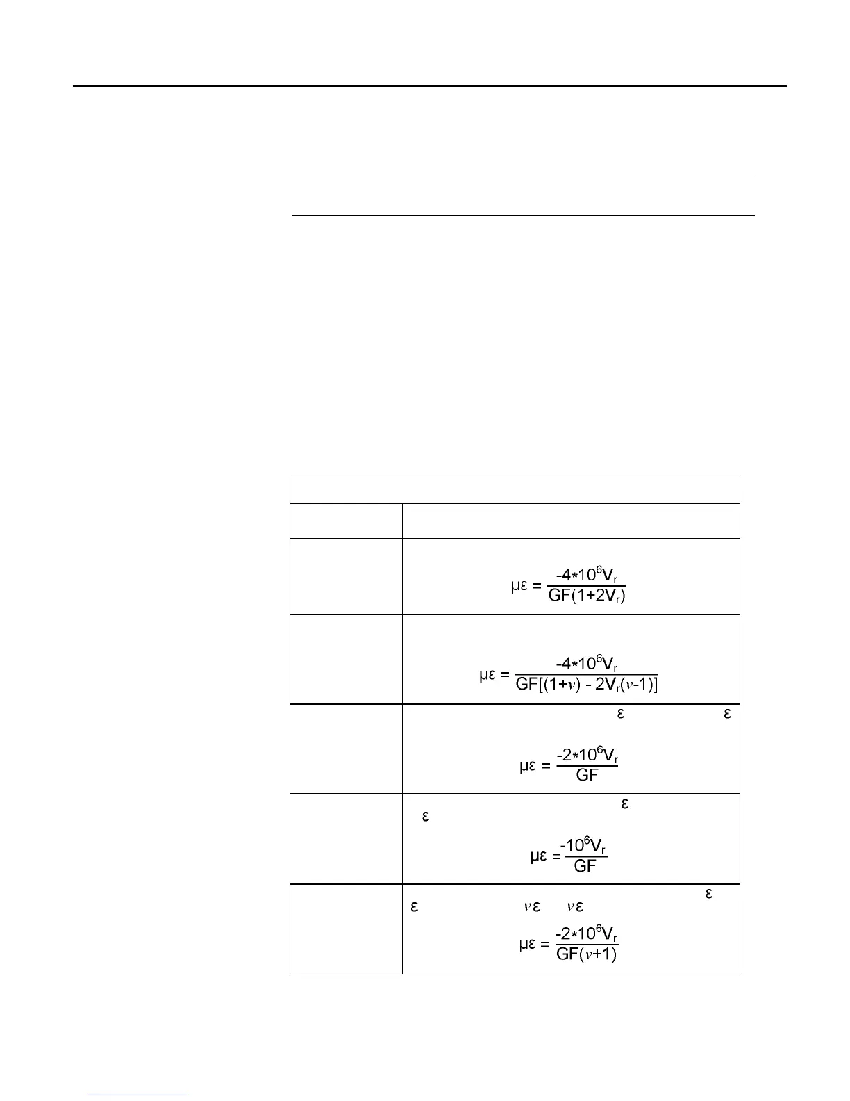
Table 63. StrainCalc() Instruction Equations
StrainCalc()
BrConfig Code
Configuration
1
Quarter-bridge strain gage:
2
Half-bridge strain gage. One gage parallel to strain, the other at 90° to
strain.
3
Half-bridge strain gage. One gage parallel to +
, the other parallel to -
:
4
Full-bridge strain gage. Two gages parallel to +
, the other two parallel
to -
:
5
Full-bridge strain gage. Half the bridge has two gages parallel to +
and
-
, and the other half to + and - :

 Loading...