Home
Campbell
Measuring Instruments
CR850
Page 53 (Figure 22: PC200 W Monitor Data Tab - Public and Onemin Tables)
Campbell CR850 - Figure 22: PC200 W Monitor Data Tab - Public and Onemin Tables; Procedure: (PC200 W Step 5)
566 pages
Manual
To Next Page
To Next Page
To Previous Page
To Previous Page
Loading...
Section 4. Quickstart Tutorial
53
4.2.5.3
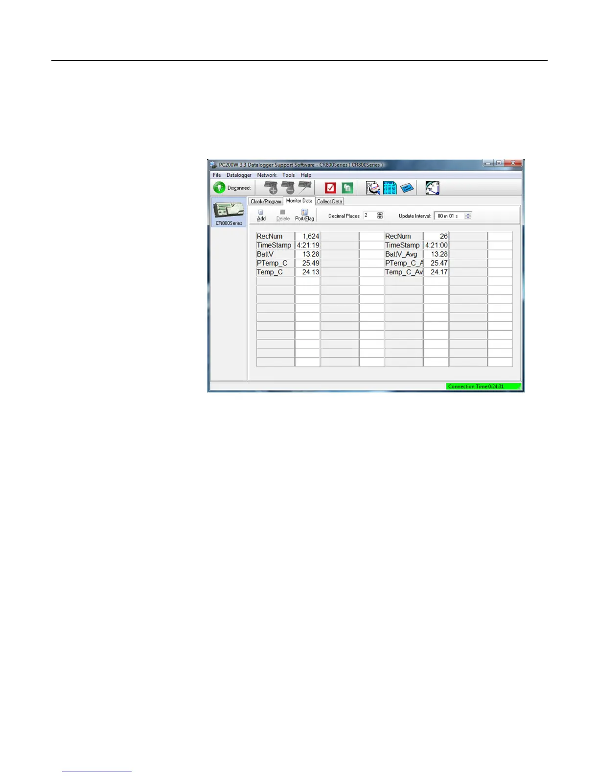
Procedure: (PC200W Step 5)
5. In
the
Add Selection
window
Tables
field, cl
ick on
OneMin
, then click
Paste
. The
On
eMin
table is now disp
layed.
Figure 22: PC200W
Monitor Da
ta
tab – Public and OneMin Tables
52
54
Table of Contents
Main Page
Default Chapter
5
About this Manual
5
Table of Contents
7
C Rbasic Example 42. Using Trigvar to Trigger Data Storage 2
24
Section 1. Introduction
27
Hello
27
Typography
27
Section 2. Cautionary Statements
29
Section 3. Initial Inspection
31
Section 4. Quickstart Tutorial
33
Primer - CR800 Data-Acquisition
33
Components of a Data-Acquisition System
33
Data Retrieval
33
Datalogger
33
Sensors
33
CR800 Module and Power Supply
34
Figure 1: Data-Acquisition System Components
34
Wiring Panel
34
Figure 2: Wiring Panel
35
Backup Battery
36
Power Supply
36
Sensors
36
Analog Sensors
36
Figure 3: Analog Sensor Wired to Single-Ended Channel #1
36
Bridge Sensors
37
Figure 4: Analog Sensor Wired to Differential Channel #1
37
Table 1. Single-Ended and Differential Input Channels
37
Voltage Excitation
37
Figure 5: Half-Bridge Wiring -- Wind Vane Potentiometer
38
Figure 6: Full-Bridge Wiring -- Pressure Transducer
38
Pulse Sensors
38
Figure 7: Pulse-Sensor Output Signal Types
39
Pulse-Input Channels
39
Pulses Measured
39
Table 2. Pulse-Input Channels and Measurements
39
Figure 8: Pulse-Input Wiring -- Anemometer Switch
40
Pulse Sensor Wiring
40
RS-232 Sensors
40
Sensors
40
Figure 10: Use of RS-232 and Digital I/O When Reading RS-232 Devices
41
Figure 9: Location of RS-232 Ports
41
Digital I/O Ports
42
SDM Channels
42
Input Expansion Modules
42
Figure 11: Control and Monitoring with Digital I/O
42
List of Figures
34
List of Tables
37
Hands-On: Measuring a Thermocouple
43
What You will Need
43
Hardware Setup
43
External Power Supply
43
PC200W Software Setup
44
Figure 12: Power and RS-232 Connections
44
Figure 13: PC200W Main Window
45
Table 3. PC200W Ezsetup Wizard Example Selections
45
Write Program with Short Cut
46
Procedure: (Short Cut Steps 1 to 6)
46
Figure 14: Short Cut Temperature Sensor Folder
47
Procedure: (Short Cut Steps 7 to 9)
47
Figure 15: Short Cut Thermocouple Wiring
48
Procedure: (Short Cut Steps 10 to 11)
48
Figure 16: Short Cut Outputs Tab
49
Procedure: (Short Cut Steps 12 to 16)
49
Figure 17: Short Cut Output Table Definition
50
Figure 18: Short Cut Compile Confirmation
50
Procedure: (Short Cut Step 17 to 18)
50
Send Program and Collect Data
51
Figure 19: PC200W Connect Button
51
Procedure: (PC200W Step 1)
51
Procedure: (PC200W Steps 2 to 4)
51
Figure 20: PC200W Monitor Data Tab – Public Table
52
Figure 21: PC200W Monitor Data Tab – Public Table
52
Figure 22: PC200W Monitor Data Tab – Public and Onemin Tables
53
Procedure: (PC200W Step 5)
53
Figure 23: PC200W Collect Data Tab
54
Procedure: (PC200W Step 6)
54
Procedure: (PC200W Steps 7 to 9)
54
Figure 24: PC200W View Data Utility
55
Figure 25: PC200W View Data Table
56
Figure 26: PC200W View Line Graph
56
Procedure: (PC200W Steps 10 to 11)
56
Procedure: (PC200W Steps 12 to 13)
56
Section 5. System Overview
57
CR800 Datalogger
58
Figure 27: Features of a Data-Acquisition System
58
Clock
59
Sensor Support
59
CR800 Wiring Panel
60
Measurement Inputs
60
Voltage Outputs
61
Grounding Terminals
62
Power in
62
Power out
62
Power Terminals
62
Communications Ports
63
Integrated Keyboard Display
63
CR1000KD Keyboard Display
64
Power Requirements
64
Programming
65
Operating System and Settings
65
User Programming
65
Memory and Final Data Storage
66
Data Retrieval
67
Data File-Formats in CR800 Memory
67
Via Mass-Storage Device
67
Via Telecommunications
67
Data Format on Computer
68
Communications
68
Pakbus
68
Custom Menus
69
DNP3 Communication
69
Keyboard Display
69
Modbus
69
Security
70
Figure 28: Custom Menu Example
70
Vulnerabilities
71
Pass-Code Lockout
72
Csipasswd
73
Passwords
73
Security By-Pass
73
File Encryption
74
IS Instructions
74
Pakbus Instructions
74
Settings
74
Communications Encryption
75
Hiding Files
75
Signatures
75
Maintenance
75
Protection from Voltage Transients
75
Protection from Water
75
Calibration
76
Internal Battery
76
Datalogger Support Software
76
Section 6. CR800 Specifications
79
Section 7. Installation
81
Moisture Protection
81
Temperature Range
81
Enclosures
81
Power Sources
82
Figure 29: Enclosure
82
Calculating Power Consumption
83
External Batteries
83
Power Supplies
83
CR800 Power Requirement
83
Vehicle Power Connections
83
Figure 30: Connecting to Vehicle Power Supply
84
Table 4. Current Source and Sink Limits
84
Continuous Regulated (5 Volt)
85
Switched Voltage Excitation
85
Continuous Unregulated (Nominal 12 Volt)
86
Grounding
86
Switched Unregulated (Nominal 12 Volt)
86
Powering Sensors and Devices
84
ESD Protection
86
Figure 31: Schematic of Grounds
88
Lightning Protection
88
Figure 32: Lightning-Protection Scheme
89
Ground Potential Differences
90
External Signal Conditioner
90
Soil Temperature Thermocouple
90
Single-Ended Measurement Reference
90
Ground Looping in Ionic Measurements
91
CR800 Configuration
92
Device Configuration Utility
92
Figure 33: Model of a Ground Loop with a Resistive Sensor
92
Figure 34: Device Configuration Utility (Devconfig)
93
Sending the Operating System
94
Sending os with Devconfig
94
Figure 35: Devconfig os Download Window
95
Figure 36: Dialog Box Confirming os Download
95
Sending os with External Memory
96
Sending os with Program Send
96
Settings
96
Settings Via Devconfig
96
Table 5. Operating System Version in Which Preserve Settings Via Program Send Instituted
96
Figure 37: Devconfig Settings Editor
97
Deployment Tab
98
Figure 38: Summary of CR800 Configuration
98
Figure 39: Devconfig Deployment Tab
98
Figure 40: Devconfig Deployment | Comports Settings Tab
100
Figure 41: Devconfig Deployment | Advanced Tab
101
Logger Control Tab
101
Figure 42: Devconfig Logger Control Tab
102
Settings Via Crbasic
102
Durable Settings
103
Include" File
103
Figure 43: "Include File" Settings Via Devconfig
104
Figure 44: "Include File" Settings Via Pakbusgraph
104
Default.cr8 File
105
Program Run Priorities
106
Figure 45: Network Planner Setup
107
Network Planner
107
Overview
107
Basics
108
Programming
108
Writing and Editing Programs
108
Short Cut Editor and Program Generator
108
Crbasic Editor
109
Inserting Comments into Program
109
Sending Programs
110
Preserving Data at Program Send
110
Figure 46: Crbasic Editor Program Send File Control Window
111
Table 6. Program Send Options that Reset Memory
111
Table 7. Data Table Structures
111
Syntax
112
Numerical Formats
112
Table 8. Formats for Entering Numbers in Crbasic
112
Table 9. Crbasic Program Structure
113
Command Line
115
Multiple Statements on One Line
115
One Statement on Multiple Lines
115
Single-Line Declarations
116
Variables
116
Table 10. Data Types
119
Constants
122
Table 11. Predefined Constants and Reserved Words
123
Alias and Unit Declarations
124
Data Tables
125
Declared Sequences
125
Table 12. TOA5 Environment Line
126
Table 13. Typical Data Table
127
Table 14. Datainterval() Lapse Parameter Options
130
Subroutines
131
Execution and Task Priority
132
Incidental Sequences
132
Pipeline Mode
133
Table 15. Task Processes
133
Sequential Mode
134
Table 16. Pipeline Mode Task Priorities
134
Execution Timing
135
Scan() / Nextscan
135
Table 17. Program Timing Instructions
135
Slowsequence / Endsequence
136
Scan Priorities in Sequential Mode
137
Subscan() / Nextsubscan
137
Figure 47: Sequential-Mode Scan Priority Flow Diagrams
139
Instructions
139
Measurement and Data-Storage Processing
139
Argument Types
140
Names in Arguments
140
Table 18. Rules for Names
140
Arrays of Multipliers and Offsets
141
Expressions in Arguments
141
Expressions
142
Expressions with Numeric Data Types
143
Floating-Point Arithmetic
143
Mathematical Operations
143
Logical Expressions
145
Table 19. Binary Conditions of TRUE and FALSE
146
String Expressions
147
Table 20. Logical Expression Examples
147
Program Access to Data Tables
148
Table 21. Abbreviations of Names of Data Processes
149
System Signatures
150
Tips
150
Use of Variable Arrays to Conserve Code Space
150
Use of Move() to Conserve Code Space
151
Programming Resource Library
151
Calibration Using Fieldcal() and Fieldcalstrain()
151
CAL Files
151
Calibration Wizard Overview
152
Crbasic Programming
152
Manual Calibration Overview
152
Single-Point Calibrations (Zero, Offset, or Zero Basis)
153
Two-Point Calibrations (Multiplier / Gain)
153
Fieldcal() Demonstration Programs
154
Table 22. Calibration Report for Air RH Sensor
154
Zero or Tare (Option 0)
154
Figure 48: Zero (Option 0)
155
Offset (Option 1)
156
Table 23. Calibration Report for Salinity Sensor
156
Zero Basis (Option 4)
157
Table 24. Calibration Report for Flow Meter
159
Two-Point Slope and Offset (Option 2)
159
Two-Point Slope Only (Option 3)
161
Fieldcalstrain() Demonstration Program
162
Figure 49: Quarter-Bridge Strain-Gage Schematic with RC-Resistor Shunt
164
Quarter-Bridge Shunt (Option 13)
165
Figure 50: Strain-Gage Shunt Calibration Started
166
Figure 51: Strain-Gage Shunt Calibration Finished
166
Figure 52: Starting Zero Procedure
166
Quarter-Bridge Zero (Option 10)
166
Information Services
167
Figure 53: Zero Procedure Finished
167
Default HTTP Web Server
168
Pakbus over TCP/IP and Callback
168
Custom HTTP Web Server
169
Figure 54: Preconfigured HTML Home
169
Figure 55: Home Page Created Using Webpagebegin() Instruction
170
Figure 56: Customized Numeric-Monitor Web
170
FTP Client
172
FTP Server
172
Ping
172
Snmp
172
Telnet
172
Dhcp
173
Dns
173
Micro-Serial Server
173
Modbus TCP/IP
173
Smtp
173
Sensor Support
173
Figure 57: Entering SDI-12 Transparent Mode
174
Transparent Mode
174
Table 25. Standard SDI-12 Command and Response Set
175
Transparent Mode Commands
175
Programmed Modes
178
Recorder Mode
178
Table 26. Sdi12Recorder() Commands
179
Sensor Mode
185
Power Considerations
186
Table 27. SDI-12 Sensor Setup -- Results
186
Table 28. Example Power Usage Profile for a Network of SDI-12 Probes
187
Subroutines
188
Wind Vector
189
Outputopt Parameters
190
Table 29. Outputopt Options
190
Wind Vector Processing
190
Calculations
191
Measured Raw Data
191
Figure 58: Mean Wind-Vector Graph
192
Figure 59: Standard Deviation of Direction
193
Custom Menus
194
Figure 60: Custom Menu Example — Home Screen
195
Figure 61: Custom Menu Example — View-Data Window
195
Figure 62: Custom Menu Example — Make-Notes Sub Menu
195
Figure 63: Custom Menu Example — Predefined-Notes Pick List
196
Figure 64: Custom Menu Example — Free-Entry Notes Window
196
Figure 65: Custom Menu Example — Accept / Clear Notes Window
196
Figure 66: Custom Menu Example — Control Sub Menu
196
Figure 67: Custom Menu Example — Control-LED Pick List
197
Figure 68: Custom Menu Example — Control-LED Boolean Pick List
197
Conditional Compilation
199
Serial I/O
201
Introduction
202
Table 30. ASCII / ANSI Equivalents
202
I/O Ports
203
Protocols
203
Table 31. CR800 Serial Ports
203
Glossary of Terms
204
Crbasic Programming
205
Input Instruction Set Basics
206
Input Programming Basics
207
Output Programming Basics
208
Translating Bytes
209
Memory Considerations
210
Demonstration Program
211
Configure Hyperterminal
212
Testing Applications
212
Figure 69: Hyperterminal New Connection Description
213
Figure 70: Hyperterminal Connect-To Settings
213
Figure 71: Hyperterminal COM-Port Settings Tab
214
Figure 72: Hyperterminal ASCII Setup
214
Create Send Text File
215
Create Text-Capture File
215
Figure 73: Hyperterminal Send Text-File Example
215
Figure 74: Hyperterminal Text-Capture File Example
215
Serial Input Test Program
215
Q & a
221
Trigvar and Disablevar - Controlling Data Output and Processing
223
NSEC Data Type
224
Figure 75: Data from Trigvar Program
224
NSEC Options
225
Bool8 Data Type
228
Figure 76: Alarms Toggled in Bit-Shift Example
229
Figure 77: Bool8 Data from Bit-Shift Example (Numeric Monitor)
229
Figure 78: Bool8 Data from Bit-Shift Example (PC Data File)
230
Faster Measurement Rates
232
Measurements from 1 Hz to 100 Hz
233
Table 32. TABLE. Summary of Analog Voltage Measurement Rates
233
Table 33. Measuring Voltse() at 1 Hz
233
Measurement Rate: 101 to 600 Hz
234
Table 34. Crbasic EXAMPLE. Measuring Voltse() at 100 Hz
234
Table 35. Measuring Voltse() at 200 Hz
234
Subscan() / Nextsubscan Details
235
Measurement Rate: 601 to 2000 Hz
236
Table 36. Measuring Voltse() at 2000 Hz
236
String Operations
237
Table 37. Parameters for Analog Burst Mode (601 to 2000 Hz)
237
String Operators
238
Table 38. String Operators
238
String Concatenation
239
String NULL Character
239
Table 39. String Concatenation Examples
239
Table 40. String NULL Character Examples
239
Extracting String Characters
240
Inserting String Characters
240
String Use of ASCII / ANSII Codes
240
Table 41. Extracting String Characters
240
Table 42. Use of ASCII / ANSII Codes Examples
240
Data Tables
241
Formatting String Hexadecimal Variables
241
Formatting Strings
241
Table 43. Formatting Strings Examples
241
Table 44. Formatting Hexadecimal Variables - Examples
241
Pulsecountreset Instruction
242
Program Signatures
243
Binary Runtime Signature
243
Executable Code Signatures
243
Text Signature
243
Advanced Programming Examples
244
Miscellaneous Features
244
Running Average and Total of Rain
247
Use of Multiple Scans
247
Groundwater Pump Test
248
Scaling Array
251
Conditional Output
252
Capturing Events
253
PRT Measurement
254
PRT Calculation Standards
254
Table 45. Prtcalc() Type-Code-1 Sensor
255
Table 46. Prtcalc() Type-Code-2 Sensor
256
Table 47. Prtcalc() Type-Code-3 Sensor
256
Table 48. Prtcalc() Type-Code-4 Sensor
257
Table 49. Prtcalc() Type-Code-5 Sensor
257
Measuring Pt100S (100-Ohm Prts)
258
PT100 in Four-Wire Half-Bridge
258
Self-Heating and Resolution
258
Table 50. Prtcalc() Type-Code-6 Sensor
258
Figure 79: PT100 in Four-Wire Half-Bridge
260
PT100 in Three-Wire Half-Bridge
260
Figure 80: PT100 in Three-Wire Half-Bridge
261
PT100 in Four-Wire Full-Bridge
262
Figure 81: PT100 in Four-Wire Full-Bridge
263
Figure 82: Running-Average Equation
264
Running Average
264
Figure 83: Running-Average Frequency Response
266
Figure 84: Running-Average Signal Attenuation
267
Measurements
269
Time
269
Time Stamps
269
Section 8. Operation
269
Voltage
270
Figure 85: PGI Amplifier
271
Figure 86: PGIA with Input Signal Decomposition
271
Input Limits
271
Reducing Error
272
Measurement Sequence
273
Measurement Accuracy
274
Timing
274
Figure 87: Voltage Measurement Accuracy (0° to 40°C)
275
Voltage Range
276
Autorange
276
Table 52. Analog Voltage Input Ranges with Options for Common Mode Null (CMN) and Open Input Detect (OID)
276
Common Mode Null / Open Input Detect
277
Fixed Voltage Ranges
277
Input and Excitation Reversal
278
Offset Voltage Compensation
278
Table 53. Analog Measurements and Offset Voltage Compensation
278
Background Calibration
279
Ground Reference Offset Voltage
279
Integration
279
Ac Power Line Noise Rejection
280
Table 54. Crbasic Measurement Integration Times and Codes
280
Table 55. Ac Noise Rejection on Small Signals
280
Figure 88: Ac Power Line Noise Rejection Techniques
281
Table 56. Ac Noise Rejection on Large Signals
281
Figure 89: Input Voltage Rise and Transient Decay
282
Signal Settling Time
282
Measuring the Necessary Settling Time
283
Minimizing Settling Errors
283
Table 57. Crbasic Measurement Settling Times
283
Figure 90: Settling Time for Pressure Transducer
285
Self-Calibration
285
Table 58. First Six Values of Settling-Time Data
285
Table 59. Status Table Calibration Entries
287
Table 60. Calibrate() Instruction Results
289
Time Skew between Measurements
290
Resistance Measurements
291
Table 61. Resistive-Bridge Circuits with Voltage Excitation
292
Ac Excitation
293
Accuracy of Ratiometric-Resistance Measurements
294
Table 62. Analog Input-Voltage Range and Basic Resolution
294
Figure 91: Deriving ∆V1
295
Strain Calculations
296
Table 63. Straincalc() Instruction Equations
296
Pulse
297
Thermocouple
297
Figure 92: Pulse-Sensor Output Signal Types
298
Figure 93: Switch-Closure Pulse Sensor
298
Pulse-Input Channels (P1 - P2)
299
Table 64. Pulse-Input Channels and Measurements
299
Figure 94: Pulse-Input Channels
300
High-Frequency Pulse (P1 - P2)
300
Low-Level Ac (P1 - P2)
300
Switch Closure (P1 - P2)
300
High Frequency Mode
301
Pulse Input on Digital I/O Channels C1 - C4
301
Low-Frequency Mode
302
Pulse Measurement Tips
302
Figure 95: Connecting Switch Closures to Digital I/O
303
Frequency Resolution
303
Table 65. Example. E for a 10 Hz Input Signal
304
Table 66. Frequency Resolution Comparison
304
Input Filters and Signal Attenuation
305
Pay Attention to Specifications
305
Pulse Measurement Problems
305
Table 67. Example of Differing Specifications for Pulse-Input Channels
305
Table 68. Time Constants (Τ)
305
Figure 96: Amplitude Reduction of Pulse-Count Waveform (before and after 1-Μs Time Constant Filter)
306
Table 69. Filter Attenuation of Frequency Signals
306
Period Averaging
307
Switch Bounce and NAN
307
And TTL
308
Figure 97: Input Conditioning Circuit for Period Averaging
308
Recording
308
Analog Sensor Cables
309
Cabling Effects
309
Field Calibration
309
Figure 98: Circuit to Limit Control Port Input to 5 VDC
309
Figure 99: Current Limiting Resistor in a Rain Gage Circuit
309
Pulse Sensors
309
Sensors
310
Synchronizing Measurements
310
Measurement and Control Peripherals
311
Analog-Input Expansion Modules
312
Control Outputs
312
Digital I/O Ports
312
Pulse-Input Expansion Modules
312
Serial-Input Expansion Modules
312
Component-Built Relays
313
Figure 100: Control Port Current Sourcing
313
Relays and Relay Drivers
313
Analog Control / Output Devices
314
Figure 101: Relay Driver Circuit with Relay
314
Figure 102: Power Switching Without Relay
314
Low-Level Ac
315
Tims
315
Vibrating Wire
315
Memory and Final Data Storage
315
Storage Media
315
Table 70. CR800 Memory Allocation
316
Table 71. CR800 SRAM Memory
317
CPU: Drive
318
Data Storage
318
Data Table SRAM
318
Table 72. Data-Storage Drives
318
USR: Drive
318
Data File Formats
319
USB: Drive
319
Table 73. Tablefile()-Instruction Data-File Formats
320
Full Memory Reset
323
Memory Conservation
323
Memory Reset
323
File Management
324
Formatting Drives
324
Manual Data-Table Reset
324
Program Send Reset
324
Table 74. File-Control Functions
324
Data Preservation
326
File Attributes
326
Table 75. CR800 File Attributes
326
External Memory Power-Up
327
Table 76. Data-Preserve Options
327
Creating and Editing Powerup.ini
328
Table 77. Powerup.ini Commands
329
File Management Q & a
330
File Names
331
File System Errors
331
Table 78. File System Error Codes
331
Telecommunications and Data Retrieval
332
Hardware and Carrier Signal
333
Initiating Telecommunications (Callback)
333
Protocols
333
Table 79. CR800 Telecommunications Options
333
Pakbus Overview
334
Nodes: Leaf Nodes and Routers
335
Pakbus Addresses
335
Router and Leaf-Node Configuration
335
Figure 103: Pakbus Network Addressing
336
Table 80. Pakbus Leaf-Node and Router Device Configuration
336
Beacon (One-Way Broadcast)
337
Hello-Message (Two-Way Exchange)
337
Linking Pakbus Nodes: Neighbor Discovery
337
Adjusting Links
338
Hello-Request (One-Way Broadcast)
338
Maintaining Links
338
Neighbor Lists
338
Automatic Packet-Size Adjustment
339
Link Integrity
339
Pakbus Troubleshooting
339
Ping
339
Figure 104: Flat Map
340
Figure 105: Tree Map
340
Loggernet Network-Map Configuration
340
Table 81. Pakbus Link-Performance Gage
340
Traffic Flow
340
Figure 106: Configuration and Wiring of Pakbus LAN
341
LAN Wiring
341
Pakbus LAN Example
341
Figure 107: Devconfig Deployment | Datalogger Tab
342
LAN Setup
342
Figure 108: Devconfig Deployment | Comports Settings Tab
343
Figure 109: Devconfig Deployment | Advanced Tab
343
Figure 110: Loggernet Network-Map Setup: COM Port
344
Loggernet Setup
344
Table 82. Pakbus-LAN Example Datalogger-Communications Settings
344
Figure 111: Loggernet Network-Map Setup: Pakbusport
345
Figure 112: Loggernet Device Map Setup: Dataloggers
345
Pakbus Encryption
346
Alternate Telecommunications
347
Declarations
347
Dnp3
347
Overview
347
Programming for DNP3
347
Crbasic Instructions
348
Table 83. DNP3 Implementation — Data Types Required to Store Data in Public Tables for Object Groups
348
Programming for Data-Acquisition
349
Modbus
350
Overview
350
Glossary of Terms
351
Table 84. Modbus to Campbell Scientific Equivalents
351
Terminology
351
Crbasic Instructions - Modbus
352
Declarations
352
Programming for Modbus
352
Table 85. Crbasic Ports, Flags, Variables, And, Modbus Registers
352
Addressing (Modbusaddr)
353
Reading Inverse-Format Registers
353
Supported Function Codes (Function)
353
Table 86. Supported Modbus Function Codes
353
Troubleshooting
353
Converting 16-Bit to 32-Bit Longs
354
Modbus over IP
354
Modbus Tidbytes
354
Authentication
355
Web Service API
355
Command Syntax
356
Table 87. API Commands, Parameters, and Arguments
357
Browsesymbols Command
358
Data Management
358
Time Syntax
358
Table 88. Browsesymbols API Command Parameters
359
Table 89. Browsesymbols API Command Response
359
Dataquery Command
362
Table 90. Dataquery API Command Parameters
363
Control
368
Setvalueex Command
368
Table 91. Setvalueex API Command Parameters
368
Table 92. Setvalue API Command Response
369
Clock Functions
370
Clockset Command
370
Table 93. Clockset API Command Parameters
370
Table 94. Clockset API Command Response
371
Clockcheck Command
372
Table 95. Clockcheck API Command Parameters
372
Table 96. Clockcheck API Command Response
372
Files Management
374
Sending a File to a Datalogger
374
Table 97. Curl Httpput Request Parameters
374
Filecontrol Command
375
Table 98. Filecontrol API Command Parameters
376
Listfiles Command
377
Table 100. Listfiles API Command Parameters
377
Table 99. Filecontrol API Command Response
377
Table 101. Listfiles API Command Response
378
Newestfile Command
381
Support Software
382
Table 102. Newestfile API Command Parameters
382
Using the Keyboard Display
382
Table 103. Special Keyboard-Display Key Functions
383
Figure 113: Using the Keyboard / Display
384
Data Display
385
Figure 114: Displaying Data with the Keyboard / Display
385
Figure 115: Real-Time Tables and Graphs
386
Real-Time Custom
386
Real-Time Tables and Graphs
386
Figure 116: Real-Time Custom
387
Figure 117: Final-Storage Tables
388
Final-Storage Tables
388
Figure 118: Run/Stop Program
389
Run/Stop Program
389
Figure 119: File Display
390
File Display
390
Figure 120: File: Edit
391
File: Edit
391
Figure 121: Ports and Status
392
Figure 122: Settings
392
Ports and Status
392
Settings
392
Configure Display
393
Pakbus Settings
393
Set Time / Date
393
Figure 123: Configure Display
393
Program and os File Compression
393
Table 104. Typical Gzip File Compression Results
395
Section 9. Maintenance
397
Moisture Protection
397
Replacing the Internal Battery
397
Figure 124: Loosening Retention Nuts
398
Table 105. Internal Lithium-Battery Specifications
398
Figure 125: Pulling Edge Away from Panel
399
Figure 126: Removing Nuts to Disassemble Canister
399
Repair
400
Figure 127: Remove and Replace Battery
400
Section 10. Troubleshooting
403
Status Table
403
Operating Systems
403
Programming
403
Status Table as Debug Resource
403
Compileresults
404
Table 106. Warning Message Examples
404
Skippedrecord
405
Skippedscan
405
Skippedslowscan
405
Memoryfree
406
Progerrors
406
Status Table Watchdogerrors
406
Varoutofbounds
406
Watchdogerrors
406
Watchdoginfo.txt File
407
Program Does Not Compile
407
Program Compiles / Does Not Run Correctly
407
NAN and ±INF
408
Floating-Point Math, NAN, and ±INF
408
Measurements
408
Measurements and NAN
408
Voltage Measurements
408
Data Types, NAN, and ±INF
409
Table 108. Variable and FS Data Types with NAN and ±INF
409
Output Processing and NAN
410
Communications
411
411
411
Communicating with Multiple Pcs
411
Comms Memory Errors
411
Commsmemfree(1)
411
Table 109. Commsmemfree(1) Defaults and Use Example, TLS Not Active
412
Commsmemfree(2)
413
Commsmemfree(3)
413
Table 110. Commsmemfree(1) Defaults and Use Example, TLS Active
413
Power Supplies
414
Overview
414
Troubleshooting Power at a Glance
415
Diagnosis and Fix Procedures
415
Battery Test
415
Charging Regulator with Solar-Panel Test
416
Charging Regulator with Transformer Test
418
Adjusting Charging Voltage
419
Terminal Emulator
421
Figure 128: Potentiometer R3 on PS100 and CH100 Charger / Regulator
421
Table 111. CR800 Terminal Commands
422
Figure 129: Devconfig Terminal Emulator Tab
424
Serial Talk through and Sniffer
424
Section 11. Glossary
425
Terms
425
Concepts
449
Accuracy, Precision, and Resolution
449
Appendix A. Crbasic Programming Instructions
451
Program Declarations
451
Variable Declarations & Modifiers
452
Constant Declarations
453
Data-Table Declarations
453
Data-Table Modifiers
453
Data Destinations
454
Final Data Storage (Output) Processing
455
Single-Source
455
Multiple-Source
456
Single Execution at Compile
457
Program Control Instructions
457
Common Program Controls
457
Advanced Program Controls
460
Measurement Instructions
461
Diagnostics
461
Voltage
462
Thermocouples
462
Resistive-Bridge Measurements
462
Excitation
463
Pulse and Frequency
463
Digital I/O
464
Control
464
Measurement
464
465
465
Specific Sensors
465
Wireless Sensor Network
467
Peripheral Device Support
468
Processing and Math Instructions
470
Mathematical Operators
470
Arithmetic Operators
471
Bitwise Operators
471
Table 112. Arithmetic Operators
471
Compound-Assignment Operators
472
Table 113. Compound-Assignment Operators
472
Logical Operators
473
Trigonometric Functions
474
Derived Functions
474
Intrinsic Functions
474
Table 114. Derived Trigonometric Functions
474
Arithmetic Functions
475
Integrated Processing
477
Spatial Processing
478
Other Functions
479
Histograms
479
String Functions
480
String Operations
480
String Commands
481
Clock Functions
483
Voice-Modem Instructions
485
Custom Keyboard and Display Menus
486
Serial Input / Output
487
Peer-To-Peer Pakbus Communications
488
Variable Management
492
Table 115. Asynchronous-Port Baud Rates
492
File Management
493
Data-Table Access and Management
495
Information Services
496
Modem Control
499
Scada
499
Calibration Functions
500
Satellite Systems
501
Argos
501
Goes
502
Omnisat
502
Inmarsat-C
503
User Defined Functions
503
Appendix B. Status Table and Settings
505
Table 116. Common Uses of the Status Table
505
Table 117. Status-Table Fields and Descriptions
506
Table 118. CR800 Settings
518
Appendix C. Serial Port Pinouts
527
CS I/O Communications Port
527
Communications Port
527
Pin-Out
527
Power States
528
Appendix D. ASCII / ANSI Table
531
Appendix E. FP2 Data Format
535
Appendix F. Other Campbell Scientific Products
537
Sensors
537
Wired Sensors Types
537
Wireless Sensor Network
538
Sensor Input Modules
538
Analog Input Multiplexers
538
T Able 125. Wireless Sensor Modules 5
538
T Able 126. Sensors Types Available for Connection to CWS900 5
538
Pulse / Frequency Input Expansion Modules
539
Serial Input Expansion Peripherals
539
Vibrating-Wire Input Modules
539
Passive Signal Conditioners
539
Resistive Bridge TIM Modules
539
Current-Shunt Modules
540
Voltage Dividers
540
Terminal-Strip Covers
540
Cameras
540
T Able 132. Voltage Dividers 5
540
Control Output Modules
541
Digital I/O (Control Port) Expansion
541
Continuous Analog Output (CAO) Modules
541
Relay Drivers
541
Dataloggers
541
Power Supplies
542
Battery / Regulator Combination
542
T Able 139. Measurement and Control Devices 5
542
T Able 140. Battery / Regulator Combinations 5
542
Batteries
543
Battery Bases
543
Regulators
543
T Able 141. Batteries 5
543
T Able 142. CR800 Battery Bases 5
543
Primary Power Sources
544
Enclosures
544
T Able 144. Primary Power Sources 5
544
T Able 145. 24-VDC Power-Supply Kits 5
544
T Able 146. Enclosures 5
544
Telecommunications Products
545
Keyboard Display
545
Direct Serial Communications Devices
545
Ethernet Link Devices
545
Telephone
545
Private Network Radios
546
Satellite Transceivers
546
Data Storage Devices
546
Data Acquisition Support Software
546
Starter Software
546
Datalogger Support Software
547
T Able 155. Datalogger Support Software 5
547
Loggernet Suite
548
Software Tools
548
T Able 157. Software Tools 5
548
Software Development Kits
549
T Able 158. Software Development Kits 5
549
Index
551
Related product manuals
Campbell 247
18 pages
Campbell 107
25 pages
Campbell TDR100
60 pages

 Loading...