configuring this statement, the router participates in the routing process and is used as a transit node of last
resort.
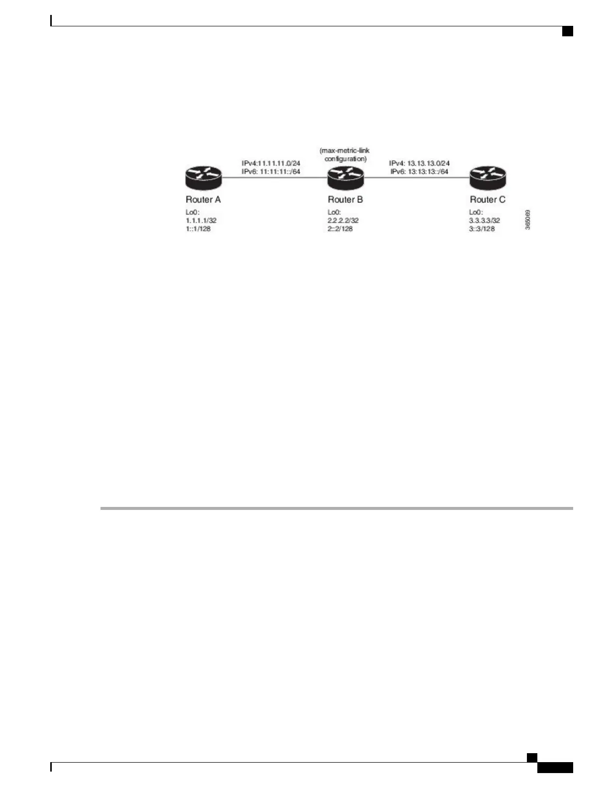
Figure 16:
Before You Begin
Ensure that you are familiar with configuring router interfaces for a given topology.
SUMMARY STEPS
1.
Configure Routers A, B, and C as shown in the topology.
2.
Configure IS-IS and the corresponding net addresses on Routers A, B and C.
3.
Configure IPv4 and IPv6 address families on the loopback interfaces of Routers A, B, and C.
4.
Configure the link metrics on the router interfaces.
5.
Confirm your configuration by viewing the route prefixes on Routers A, B, and C.
6.
Confirm the link metrics on Router B, prior to configuring the max-link-metric statement.
7.
Configure the max-link-metric statement on Router B.
8.
Commit your configuration.
9.
Confirm the change in link metrics on Router B.
10.
(Optional) Verify the change in route prefixes on Routers A and C.
DETAILED STEPS
Step 1
Configure Routers A, B, and C as shown in the topology.
Use the following IP Addresses:
•
Router A Loopback0: 1.1.1.1/32 and 1::1/128
•
Router A -> Router B: 11.11.11.2/24 and 11:11:11::2/64
•
Router B Loopback0: 2.2.2.2/32 and 2::2/128
•
Router B -> Router A: 11.11.11.1/24 and 11:11:11::1/64
•
Router B-> Router C: 13.13.13.1/24 and 13:13:13::1/64
•
Router C Loopback0: 3.3.3.3/32 and 3::3/128
•
Router C-> Router B: 13.13.13.2/24 and 13:13:13::2/64
Step 2
Configure IS-IS and the corresponding net addresses on Routers A, B and C.
Cisco ASR 9000 Series Aggregation Services Router Routing Configuration Guide, Release 5.3.x
397
Implementing IS-IS
Example: Configuring IS-IS To Handle Router Overload

 Loading...


