19-10
Catalyst 3750-E and 3560-E Switch Software Configuration Guide
OL-9775-08
Chapter 19 Configuring MSTP
Understanding RSTP
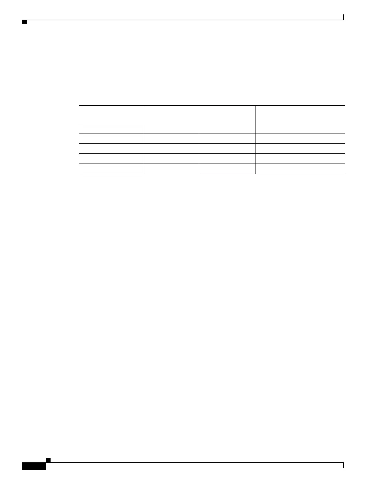
In a stable topology with consistent port roles throughout the network, the RSTP ensures that every root
port and designated port immediately transition to the forwarding state while all alternate and backup
ports are always in the discarding state (equivalent to blocking in IEEE 802.1D). The port state controls
the operation of the forwarding and learning processes. Table 19-2 provides a comparison of
IEEE 802.1D and RSTP port states.
To be consistent with Cisco STP implementations, this guide defines the port state as bl
ocking instead
of discarding. Designated ports start in the listening state.
Rapid Convergence
The RSTP provides for rapid recovery of connectivity following the failure of a switch, a switch port, or
a LAN. It provides rapid convergence for edge ports, new root ports, and ports connected through
point-to-point links as follows:
• Edge ports—If you configure a port as an edge port on an RSTP switch by using the spanning-tree
portfast interface configuration command, the edge port immediately transitions to the forwarding
state. An edge port is the same as a Port Fast-enabled port, and you should enable it only on ports
that connect to a single end station.
• Root ports—If the RSTP selects a new root port, it blocks the old root port and immediately
transitions the new root port to the forwarding state.
• Point-to-point links—If you connect a port to another port through a point-to-point link and the local
port becomes a designated port, it negotiates a rapid transition with the other port by using the
proposal-agreement handshake to ensure a loop-free topology.
As shown in Fi
gure 19-4, Switch A is connected to Switch B through a point-to-point link, and all
of the ports are in the blocking stat
e. Assume that the priority of Switch A is a smaller numerical
value than the priority of Switch B. Switch A sends a proposal message (a configuration BPDU with
the proposal flag set) to Switch B, proposing itself as the designated switch.
After receiving the proposal message, Switch B selects as its new root port the port from which the
pr
oposal message was received, forces all nonedge ports to the blocking state, and sends an
agreement message (a BPDU with the agreement flag set) through its new root port.
After receiving Switch B’s agreement m
essage, Switch A also immediately transitions its designated
port to the forwarding state. No loops in the network are formed because Switch B blocked all of its
nonedge ports and because there is a point-to-point link between Switches A and B.
Ta b l e 19-2 Port State Comparison
Operational Status
STP Port State
(IE
EE 802.1D) RSTP Port State
Is Port Included in the
Active Topology?
Enabled Blocking Discarding No
Enabled Listening Discarding No
Enabled Learning Learning Yes
Enabled Forwarding Forwarding Ye s
Disabled Disabled Discarding No