5-20
Catalyst 3750-E and 3560-E Switch Software Configuration Guide
OL-9775-08
Chapter 5 Managing Switch Stacks
Configuring the Switch Stack
Configuring the Switch Stack
These sections contain this configuration information:
• Default Switch Stack Configuration, page 5-20
• Enabling Persistent MAC Address, page 5-20
• Assigning Stack Member Information, page 5-22
Default Switch Stack Configuration
Table 5-3 shows the default switch stack configuration.
Enabling Persistent MAC Address
The switch stack MAC address is determined by the MAC address of the stack master. When a stack
master is removed from the stack and a new stack master takes over, the default is for the MAC address
of the new stack master to immediately become the new stack MAC router address. However, you can
enable the persistent MAC address feature to allow a time delay before the stack MAC address changes.
During this time period, if the previous stack master rejoins the stack, the stack continues to use its MAC
address as the stack MAC address, even if the switch is now a stack member and not a stack master. If
Stack master failure Remove (or power off) the stack master. Based on the factors described in the “Sta
ck Master
Election and Re-Election” section on page 5-5, one
of the remaining stack members becomes the new
sta
ck master. All other stack members in the stack
remain as stack members and do not reboot.
Add more than nine stack
mem
bers
1. Through their StackWise Plus ports,
connect ten switches.
2. Power on all switches.
Two switches become stack masters. One stack
ma
ster has nine stack members. The other stack
master remains as a standalone switch.
Use the Mode button and port LEDs on the switches
to
identify which switches are stack masters and
which switches belong to each stack master. For
information about using the Mode button and the
LEDs, see the hardware installation guide.
Table 5-2 Switch Stack Configuration Scenarios (continued)
Scenario Result
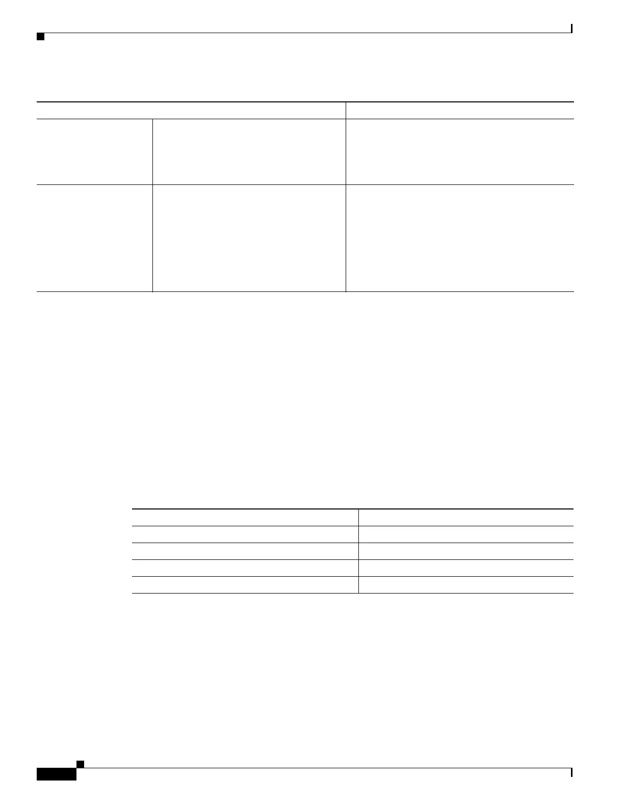
Ta b l e 5-3 Default Switch Stack Configuration
Feature Default Setting
Stack MAC address timer Disabled.
Stack member number 1
Stack member priority value 1
Offline configuration The switch stack is not provisioned.