Removal and replacement of ADU modules
99-145912-A Chapter 8: Service & maintenance 8-17
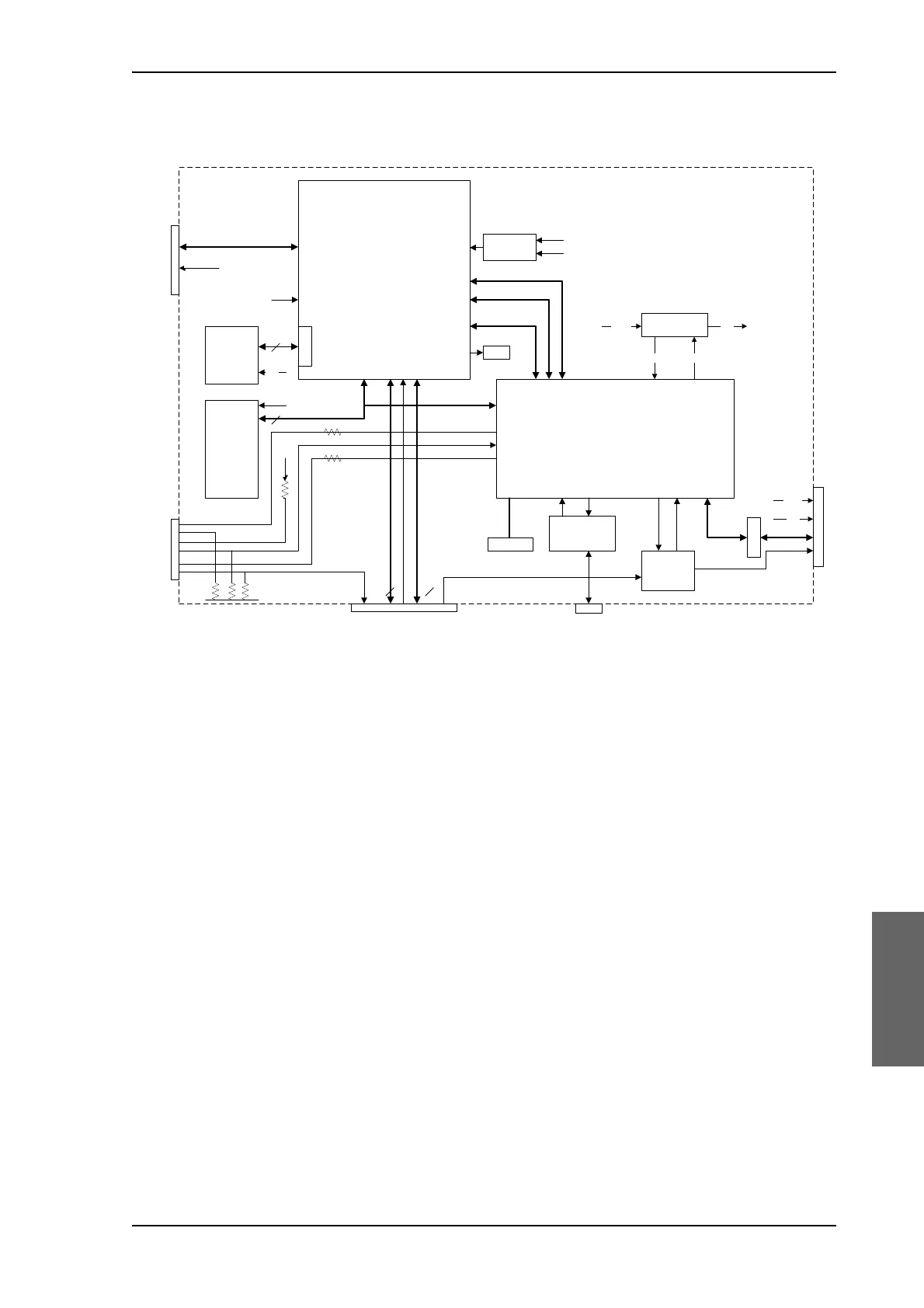
3. Pedestal Control Module (PCM).
The PCM will - based on several inputs - control the position of the
parabolic reflector and the polarization angle of the polarisation
mechanism assembly via 3 brush less DC-motors and a stepper
motor.
The PCM board is:
• Modem communication with a below deck Antenna Control Unit
via a VSAT interface module (VIM).
• Control of the VIM module devices via a parallel interface
connector.
• Communication master of the ADU Bus connecting to the DC-
motor Driver Modules (DDM), the Polarization Motor Module
(PMM), and the Inertial Sensor Module (ISM).
• Communication with the GPS module.
• Provide power to the modules connected via the ADU bus (motor
drivers supplies and bus interface circuits' supplies) with over-
current protection (hot swap) via the bus cable.
• Modules are by means of shielded DB9 cables connected in a
chain in the following order: PCM — DDM (azimuth) — DDM (X-
elevation) — DDM (elevation) — ISM — BCM (BUC Control
Module). The BCM contains signal terminations.
4. Service switch.
Figure 8-11: PCM – Block diagram
3&0
6%XV
3HGHVWDO &RQWURO 0RG OH
6XE'KLJKGHQVLW\
&6JDWHV
9ROWDJH
6XSHUYLVRU
)3*$
'63
6'5$0
%8&B2Q
/('V
0LFURILWS
*36
0RGXOH
$'8$&8
0RGHP
0RGXODWLRQ
'HPRGXODWLRQ
%8&B6ZB2Q
60$
90
90VWDWXV
56
9
9
6XE'
5[ 7[
6ZB2Q
9PRWRUB2Q
9*36
9SVP
(0,)%
9,0 9,0
'63)3*$
DSSOLFDWLRQ
LPDJHV
$QWHQQD,'
&RQILJXUDWLRQ
&ON
+RWVZDS
9
9
*36B5[*36B7[
WHPSVHQV
0LFURILWS
6HUYLFH
6ZLWFK
6ZB/('
9
9V
6WDWXV 9VB2Q
9V9SVP
9DGU

 Loading...


