EasyManuals Logo

COBHAM SAILOR 100 GX User Manual

COBHAM SAILOR 100 GX
252 pages
To Next Page IconTo Next Page
To Previous Page IconTo Previous Page
Page #139 background imageLoading...
Page #139 background image
Removal and replacement of ADU modules
99-145912-A Chapter 8: Service & maintenance 8-25
Service & maintenance
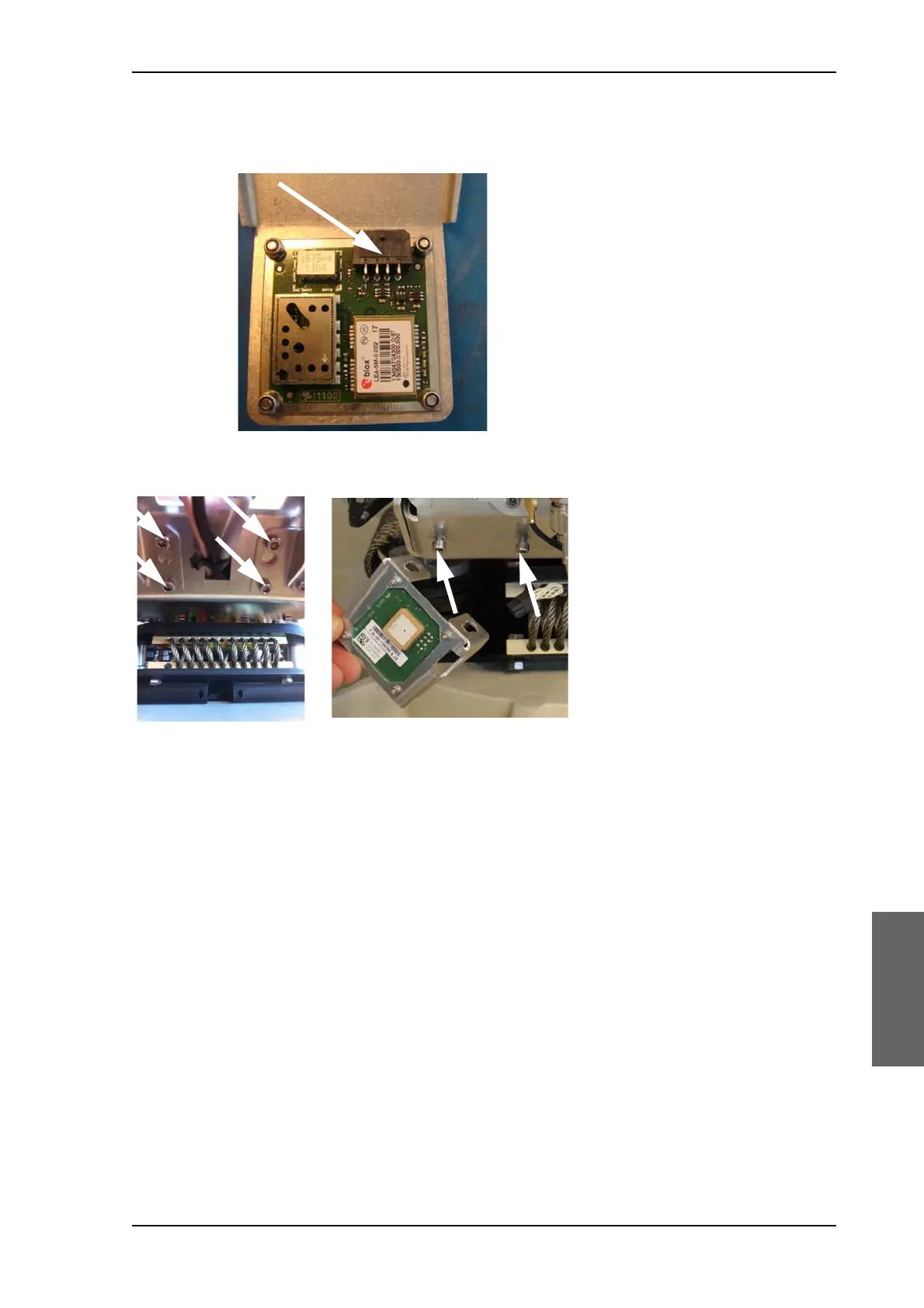
4. Disconnect the connector located on the bottom side of the GPS
PCB.
5. Loosen the 4x4 mm Allen screws (thread size M5).
6. Lift the complete GPS module free, in the key holes, from the
pedestal.
To insert a new GPS module follow the instructions above in reverse
order.
Figure 8-20: Connector for GPS PCB
Figure 8-21: Screws on GPS module

Table of Contents

Other manuals for COBHAM SAILOR 100 GX

Questions and Answers:

Question and Answer IconNeed help?

Do you have a question about the COBHAM SAILOR 100 GX and is the answer not in the manual?

COBHAM SAILOR 100 GX Specifications

General IconGeneral
BrandCOBHAM
ModelSAILOR 100 GX
CategoryMarine Equipment
LanguageEnglish

Related product manuals