EasyManuals Logo

COBHAM SAILOR 100 GX User Manual

COBHAM SAILOR 100 GX
252 pages
To Next Page IconTo Next Page
To Previous Page IconTo Previous Page
Page #141 background imageLoading...
Page #141 background image
Removal and replacement of ADU modules
99-145912-A Chapter 8: Service & maintenance 8-27
Service & maintenance
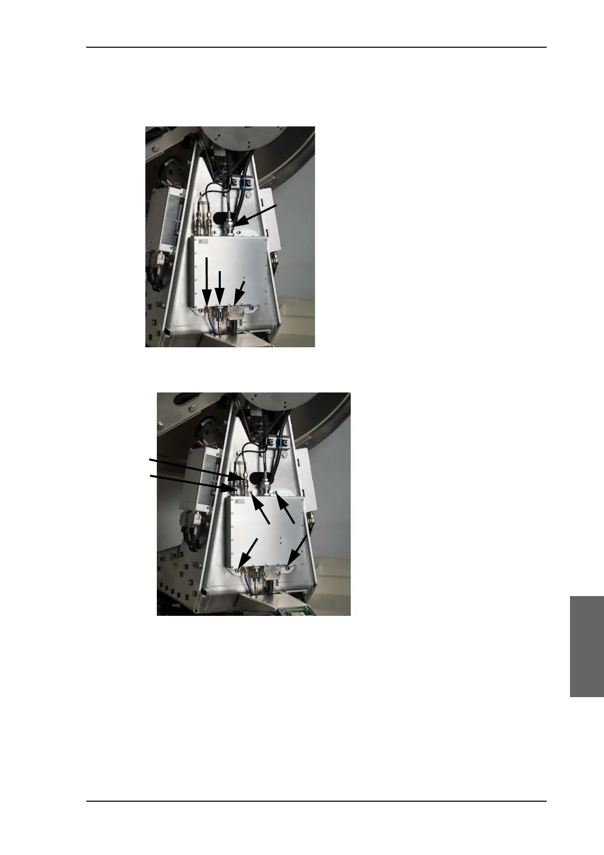
7. Disconnect the N-connector at the top (A) and the one at the bottom
of the VIM (B), the SUB-D-connector (C), then the SMA connector
(D) at the bottom of the VIM2.
8. Loosen the 4x4 mm Allen screws to remove the VIM.
9. Insert the new VIM2 module, follow the instructions above in reverse
order. Use the cable wrench where appropriate.
10.Connect the cable X POL to B and CO POL to A.
Figure 8-24: Replacement of the VIM (Continued)
Figure 8-25: Replacing the VIM — remove 4 Allen screws
A (2 Nm)
D (1 Nm)
B (2 Nm)
C (manual)
(2.5 Nm)

Table of Contents

Other manuals for COBHAM SAILOR 100 GX

Questions and Answers:

Question and Answer IconNeed help?

Do you have a question about the COBHAM SAILOR 100 GX and is the answer not in the manual?

COBHAM SAILOR 100 GX Specifications

General IconGeneral
BrandCOBHAM
ModelSAILOR 100 GX
CategoryMarine Equipment
LanguageEnglish

Related product manuals