Removal and replacement of ADU modules
99-145912-A Chapter 8: Service & maintenance 8-47
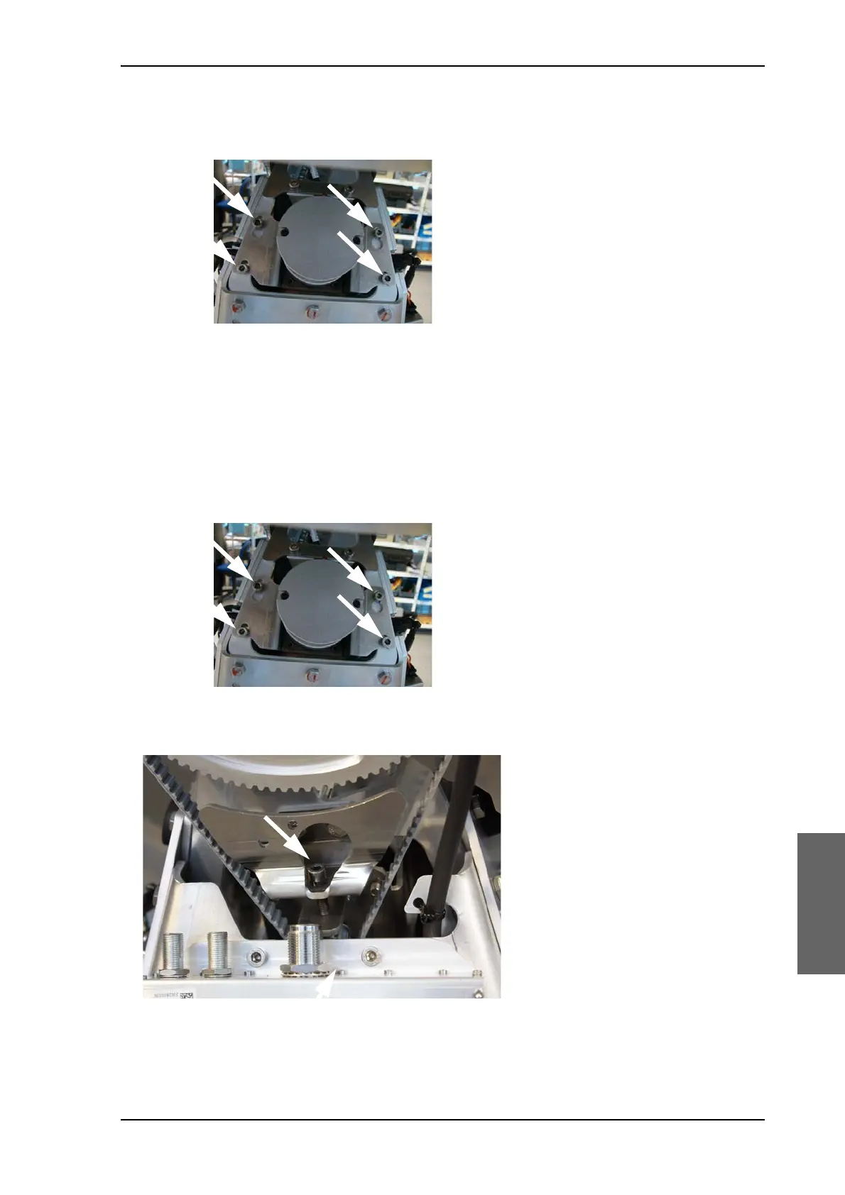
8. Loosen the 4x4 mm Allen screws (thread size M5) of the motor
assembly.
9. Lift the complete X Elevation Motor & Encoder assembly free, in the
key holes, from the pedestal and remove it.
To insert a new X Elevation Motor & Encoder follow the instructions
above in reverse order while observing the following mounting
guidelines:
1. Do not tighten the 4x4 mm Allen screws (thread size M5) of the
motor assembly.
2. Adjust the belt tension using the belt tension/adjustment screw.
Figure 8-57: X Elevation motor assembly, 4 Allen screws
Figure 8-58: Cross Elevation motor assembly, do not tighten screws
Figure 8-59: X-Elevation Motor & Encoder — adjust belt tension

 Loading...


