Removal and replacement of ADU modules
8-66 Chapter 8: Service & maintenance 99-145912-A
1. Open the service hatch.
2. Switch off the power to the antenna on the service switch.
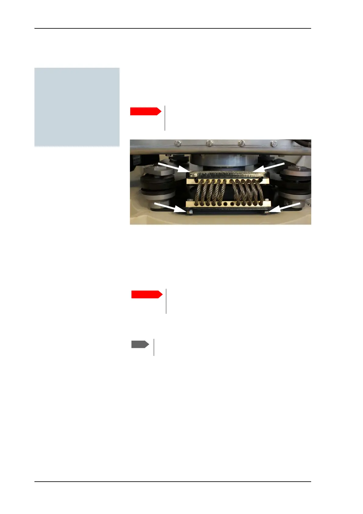
3. Loosen the 4 x M6 hexagonal head screws that connect the wire
rope isolator to the antenna.
4. Slowly push or pull the x elevation level-beam upwards in order to
tilt the antenna and hereby releasing the wire rope isolator from the
two plates.
5. Remove the old wire rope isolator and replace it with a new one.
6. Apply Loctite 243 to the 4 x M6 hexagonal head screws and fasten
the new wire rope isolator to the top and bottom plate.
7. Repeat the procedure for each wire rope isolator that needs
replacing.
Tools needed:
•TX20
• 4 x 150 mm Allen key
(located inside the service
door of the ADU)
• 10 mm wrench
•Loctite 243
Loosen only one wire rope isolator at a time! Two
loose isolators will make the antenna very unstable
with a high risk of damage.
Figure 8-86: Removing a wire-rope isolator
Before tilting back the antenna to its original
position make sure to keep fingers and tools well
away from the contact zones.
Loctite on the screws is essential in order to secure a
rigid connection over time.

 Loading...


