ComNav P4 Installation and Operation
Document PN 29010100 V1r0 - 19 -
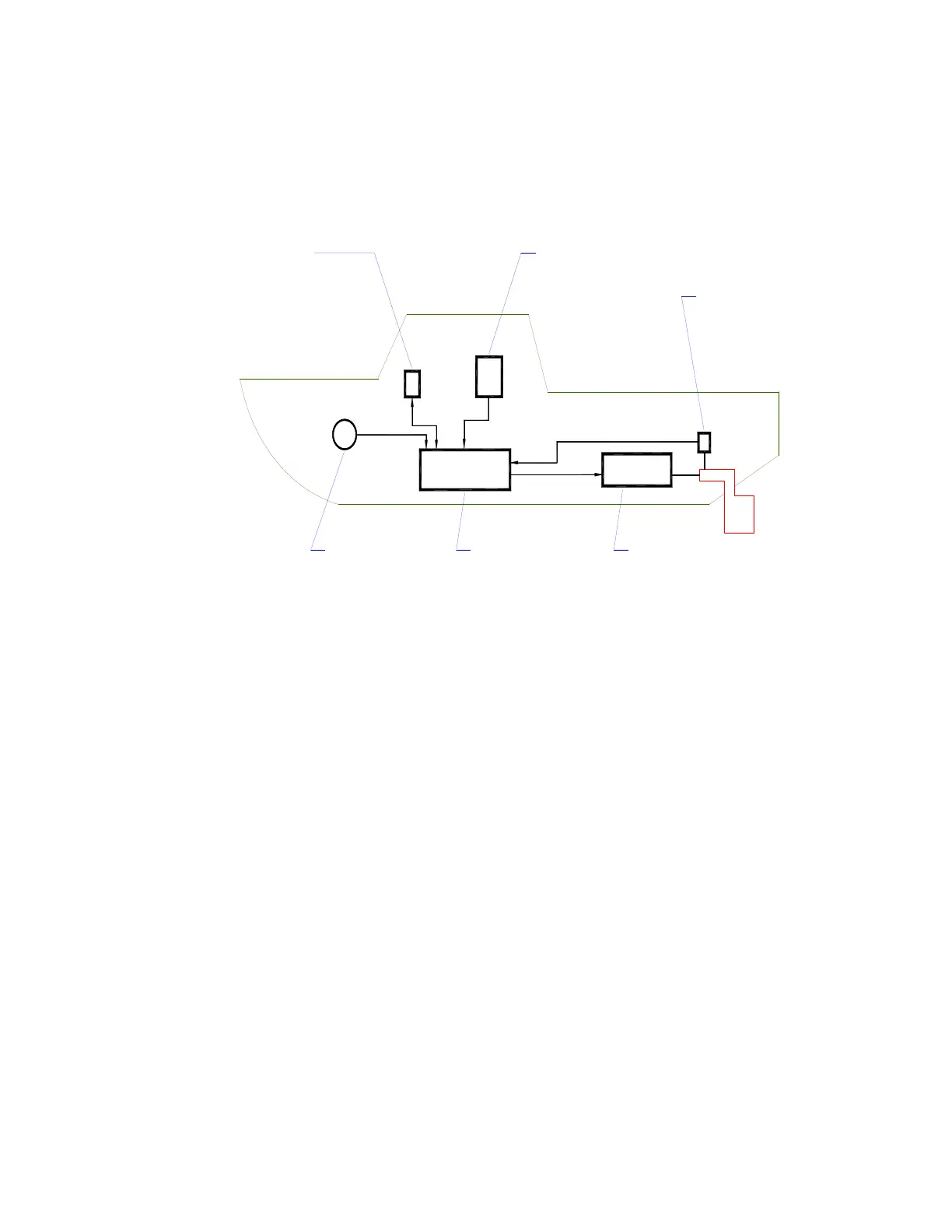
Basic Autopilot System
Figure 1 is a block diagram of the major components of an autopilot system.
COMPASS
READS THE VESSEL'S
ACTUAL HEADING AND
SENDS IT TO THE SPU
PROCESSOR (SPU)
CALCULATES THE RUDDER
POSITION NEEDED TO STEER
THE VESSEL ON THE DESIRED
HEADING, AND CONTROLS THE
STEERING SYSTEM
ACCORDINGLY
STEERING SYSTEM (ACTUATOR)
[HYDRAULIC RAM OR ELECTRIC MOTOR
WHICH IS MECHANICALLY CONNECTED
TO THE RUDDER]
MOVES THE RUDDER IN RESPONSE TO
CONTROL SIGNALS FROM THE SPU
RUDDER FOLLOWER UNIT (RFU)
[MECHANICALLY CONNECTED TO RUDDER]
MEASURES RUDDER POSITION AND SENDS
IT TO THE SPU
NAVIGATION DEVICES
[OPTIONAL]
SUPPLY NAVIGATION
INFOMRATION TO THE SPU
IN NMEA 0183 FORMAT
CONTROL HEAD
DISPLAYS STATUS AND HEADING
INFORMATION FROM THE SPU, AND
ALLOWS THE OPERATOR TO INPUT
STEERING COMMANDS & OPERATING
PARAMETERS
Figure 1 – Basic Autopilot System
The Compass indicates the direction in which the boat is pointed, often referred to as the
Actual Heading. Depending on the type of boat and installed equipment, the Compass may
be a magnetic compass, an electronic fluxgate compass, a gyroscopic compass, or a GPS
Compass.
• A reliable compass is absolutely vital to the autopilot; without a trusted compass, the
autopilot has no way of knowing where the boat is, or which way it is headed.
The actual heading is fed electronically from the Compass to the Signal Processor Unit
(SPU), which is the heart of the autopilot. The SPU contains the microcontroller(s), electronic
hardware, and the sophisticated control software necessary to steer the boat on any desired
Heading.
The Control Head, normally located in the wheelhouse, is the interface between the vessel’s
operator and the autopilot. The Control Head displays information about what
the autopilot is
doing, and it has various controls (buttons and/or knobs) that allow you to give
commands to
the autopilot.