ComNav P4 Installation and Operation
Document PN 29010100 V1r0 - 52 -
Wiring the System
Power Supply
The ComNav P4 will operate on any voltage of 12 VDC and 30 VDC. This allows operation with
vessel battery systems of nominal voltages from 12 to 24 VDC.
Caution! Do not power up the SPU until you have completed the installation, and
performed the steps outlined in “Post-Installation Checks.”
Generally, wiring for the positive leg of a DC system will be red or white, while wiring for the
negative leg (usually referred to as Ground) will be black.
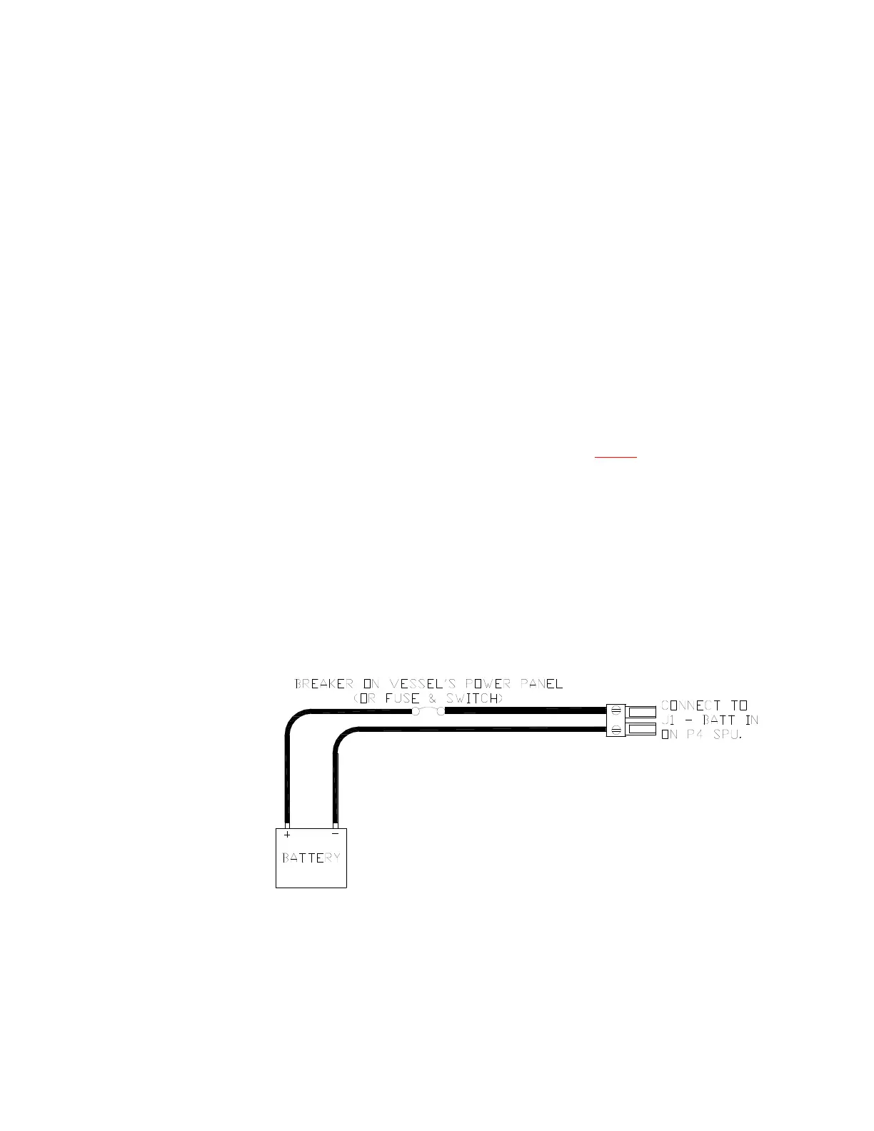
Power to supply the autopilot should be taken directly from a breaker or distribution panel. The
autopilot should be wired into its own individual breaker or fuse. For the P4 SPU, using
appropriately sized wire or cable (see Table 1), wire the battery connections to the connector
plug and receptacle labelled J1 - BATTERY INPUT OF THE SPU. For the P4 Control Head, connect
the Head Power Cable to the 4 pin receptacle on the back of the Head. Double-check the wiring
polarity before inserting the plug into the receptacle.
Caution! The P4 SPU & the P4 Head are NOT reverse-polarity
protected. If you wire the wrong voltage polarity at J1, you will
damage the SPU and Control Head! This will void the warranty.
Refer to the following diagram of a typical power supply circuit:
Figure 23 – Typical Battery Connection to SPU
Installation