ComNav P4 Installation and Operation
Document PN 29010100 V1r0 - 67 -
Signal Names
The names of the NMEA data signals, and of the paired wires carrying them (see Table 3),
are
specified in NMEA 0183: `A´ and `B´. The SPU’s wiring label uses those names, on the
J9– NAV I/O connector (see Figure 30).
However, sometimes other equipment will use
different names:
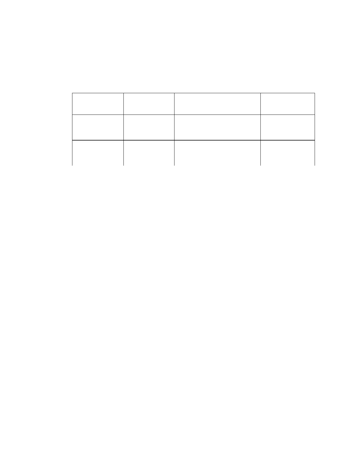
Table 3 – NMEA Signal Translation Guide
RS-422 Electrical Interface
The RS-422 electrical interface specified in the NMEA 0183 Standard uses a pair of
balanced
signals (also known as “differential signals”), in paired wires, with the ‘A’ signal on
one wire and the
complementary ‘B’ signal on the other.
It is necessary to maintain the correct signal polarity, when connecting one of the P4
SPU’s RS-422 input or output wire pairs to another NMEA 0183 device:
The P4 input port’s `A´ signal pin must be connected to the `A´ output
terminal of the
other device; similarly, the P4’s `B´ input pin must be
connected to the `B´ output
terminal of the other device.
Similarly, the P4 output port’s `A´ and `B´ signal pins must be connected to the
`A´ and `B´ input terminals of the other device.
Other points to be aware of:
There is no ground wire for the P4’s NAV1 - IN ports. Both ports are NMEA
Listeners
(as defined in the Standard), and so are optically isolated from the
rest of the SPU
circuitry; they need only the `A´ and `B´ signal pair to function
properly.
The P4’s NAV - OUT port (an NMEA Talker) is not optically isolated from the
rest of
the SPU circuitry. However, since the other device will have an
optically-isolated
input (if it is a fully-compliant NMEA Listener), no ground
wire for the NAV - OUT port is necessary.
The CH pin on J6 is connected directly to the SPU chassis, and is also AC-
connected
to the SPU’s Signal Ground, via a 100 nF capacitor. If the cable
carrying the NAV
signal wires from/to the other NMEA device is shielded, the
shield should be wired to
the CH pin (the cable’s shield must not be connected
at the other end, or anywhere else
but to the J6 CH pin).
Positive voltage with respect
to `B´ is a logical 0
(aka Active or Space or ON
17
)
+ or NMEA +
SIG or SIGNAL
POS or +VE
Positive voltage with respect
to `A´ is a logical 1
(aka Idle or Mark or OFF)
- or NMEA -
RTN or RETURN
NEG or -VE
Installation