ComNav P4 Installation and Operation
Document PN 29010100 V1r0 - 62 -
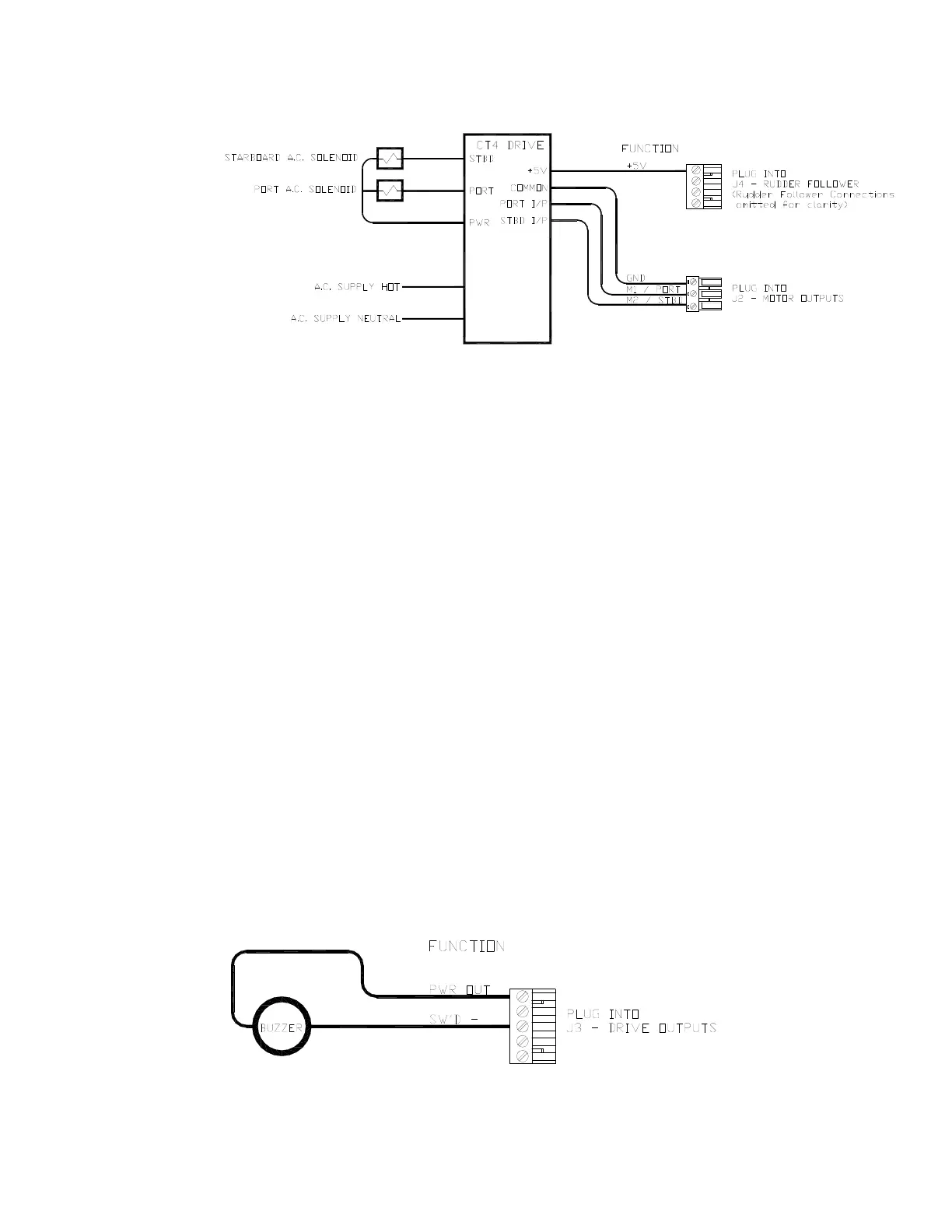
Figure 39 – Wiring Connections for AC solenoids
Azimuth Drives, Surface Piercing Drives and Jet Drives
The ComNav CT7 Thruster Interface is used with Azimuth Drives, Surface Piercing Drives and
Jet Drives requiring a 10 Volt +/- proportional analog command signal. See the CT7’s
Installation and Operation Manual for wiring instructions, in the Rudder Drives and Interfaces
section referencing Figure 16.
External Alarm Output
An external alarm can be connected to the P4 SPU. The autopilot can be configured to activate
this alarm whenever an alert or error message appears on the Control Head. You can modify
the configuration to activate the external alarm only if the Watch Alarm is not answered (as
opposed to activating it for all alarms).
One of two outputs can be used for the external alarm. Typically, you would choose to connect
the external alarm between Battery Positive (PWR OUT) and the Switched B- (SW’D B-) outputs
on J2. See the diagrams in Figure 40 and Figure 41 for information on how to select these
options.
Figure 40 – External Alarm, using SW'D B- Output
Installation