ComNav P4 Installation and Operation
Document PN 29010100 V1r0 - 57 -
Compasses
All compasses, other than NMEA 0183 compasses, are connected to the SPU receptacle
labelled J9 – COMPASS (see the Compass section for how to connect NMEA compasses).
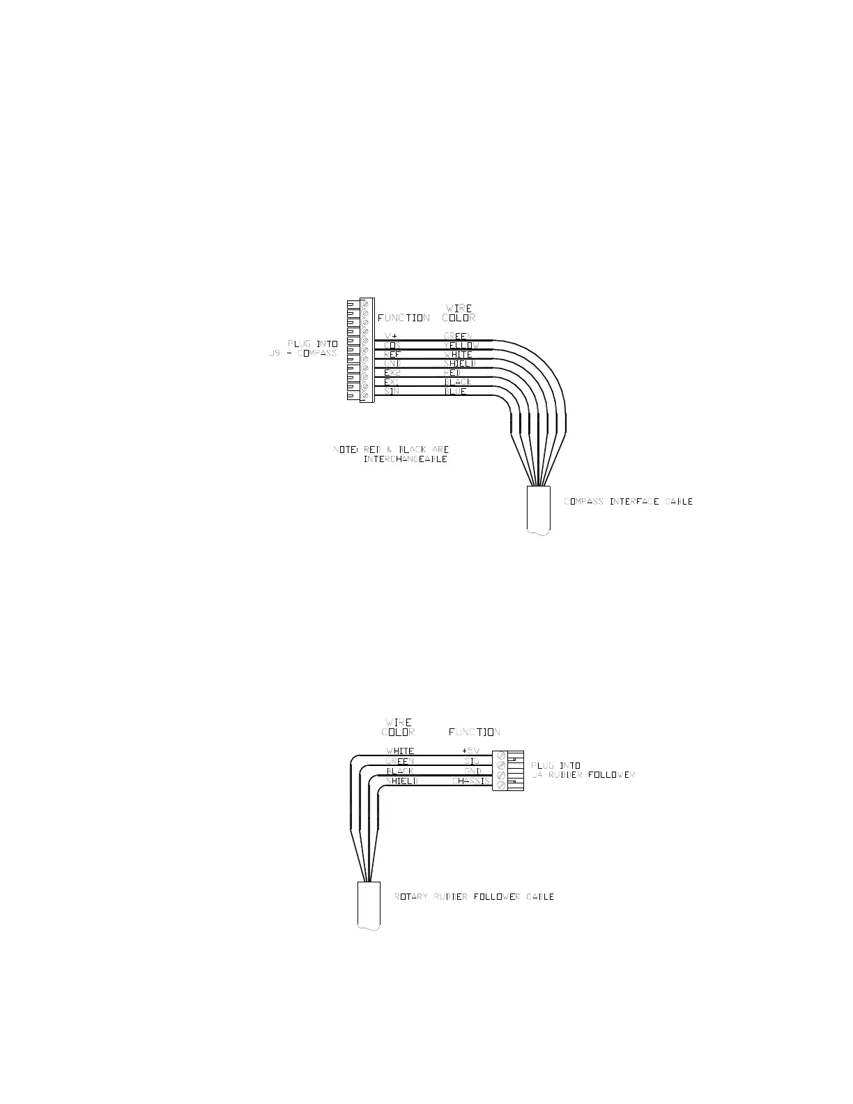
If you ordered your P4 system with a ComNav Fluxgate Compass, the cable wires connect to
the J9 receptacle, as per the diagram in Figure 30.
If you ordered your system with the Magnetic Sensor, and mounted it on the bottom of your
magnetic compass, you will also need to wire the flying-lead end of the sensor cable as per the
diagram in Figure 30. If you mounted the sensor of top of the compass, simply exchange the
blue and yellow wires.
Figure 30 – Wiring Connections for Analog Compasses
Rudder Follower
The Rudder Follower is connected to the four-position receptacle on the SPU labelled
J4 – RUDDER FOLLOWER. Wire the Rudder Follower to the plug-in connector as per the following
diagram in Figure 31.
Figure 31 – Wiring Connections for Rudder Followers
Installation